Tag: color

Rollei / Compard Digibase C-41 Processing Kit

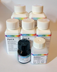
I just received this great C-41 process developing kit (I got the 20 roll kit) from freestylephoto.biz and I’m diving head-first in to processing my own color film for the first time.

The process seems only a bit little more complicated than black and white and the Rollei / Digibase chemicals have the advantage of being useable at an easy to maintain 25°C.

I put this page together as a cheat-sheet for myself and most of the information here can be found in the Rollei / Compard Digibase C-41 Processing Kit Instruction Guide [PDF]

Mixing the Chemicals

The 500 ml capacity that is most useful to me (I usually process either a single 120 or two 35mm rolls at a time in a Paterson tank) is not included in the Rollei instructions. 460 ml and 480 ml are there but 500 ml is nowhere to be found. I worked out the 500 ml solution by halving the 1000 ml concentrations listed in the instructions.

For 500 ml I used half of all the developer solution and bleach (which is a bright algae green in concentrate), ¾’s of the fixer and all of the stabilizer. The 50 ml of stabilizer included in the kit will only make a 500 ml working solution. You’d need 100 ml to make 1 liter of working solution. (The 500 ml working solution will work for 30 rolls, which is more than the developer should last anyway…)

Note that the water temperature needs to be at 49°C for proper mixing of the chemicals. I used a kettle to bring the water up to temperature and had my mixing graduates in a water bath at roughly 50°C to maintain temperature while mixing.

Developer
Working Solution
Water
Part A
Part B
Part C
Starter
Film Capacity*
300 ml
207 ml
30 ml
30 ml
30 ml
3 ml
4 -6 rolls
500 ml
345 ml
50 ml
50 ml
50 ml
5 ml
7 – 11 rolls
1000 ml
690 ml
100 ml
100 ml
100 ml
10 ml
12 – 20 rolls
* 35mm, 36 exposure or 120 format rolls
Bleacher
Working Solution
Water
Bleach
Film Capacity*
300 ml
216 ml
84 ml
6 – 9 rolls
500 ml
360 ml
140 ml
10 – 19 rolls
1000 ml
720 ml
280 ml
20 – 28 rolls
* 35mm, 36 exposure or 120 format rolls
Fixer
Working Solution
Water
Fixer
Film Capacity*
300 ml
240 ml
60 ml
6 – 9 rolls
500 ml
400 ml
100 ml
10 – 19 rolls
1000 ml
800 ml
200 ml
20 – 28 rolls
* 35mm, 36 exposure or 120 format rolls
Stabilizer
Working Solution
Water
Stabilizer
Film Capacity*
300 ml
270 ml
30 ml
18 rolls
500 ml
450 ml
50 ml
30 rolls
1000 ml
900 ml
100 ml
60 rolls
* 35mm, 36 exposure or 120 format rolls

The Developing Process

The processing order is Pre-Soak -> Developer -> Bleach -> Wash -> Fixer -> Stabilizer

Development can be done at a range of temperatures with this kit and several are provided in the instructions.

The temperatures I’ve tried so far are the “rapid” at 45°C and the lower one at 25°C. The lower temperature is easier to maintain but time to develop takes 33½ minutes versus 11½ minutes when done at 45°C.

Pre-Soak
Temperature
Time
Agitation
25°C
3 min
15 seconds of continuous agitation at start, then 1 agitation every 30 seconds thereafter
45°C
2 min
Developer
Temperature
Time
Agitation
25°C
13 min
Agitate once every 30 seconds
45°C
2 min
15 seconds of continuous agitation at start, then 1 agitation every 30 seconds thereafter
Bleach
Temperature
Time
Agitation
25°C
6 min
Agitate once every 30 seconds
45°C
2 min
15 seconds of continuous agitation at start, then 1 agitation every 30 seconds thereafter
Wash
Temperature
Time
Agitation
25°C
3 min
15 seconds of continuous agitation at start, then 1 agitation every 30 seconds thereafter
45°C
2 min
Fixer
Temperature
Time
Agitation
25°C
7 min
Agitate once every 30 seconds
45°C
2 min 30 sec
Stabilizer
Temperature
Time
Agitation
25°C
1 min 30 sec
Agitate once every 30 seconds
40°C
1 min
15 seconds of continuous agitation at start, then 1 agitation every 30 seconds thereafter

StarlightXpress MX7C to MX716 Conversion

Sony ICX249AK (color) and ICX249AL (mono)

Shortly after I bought my MX7C I read that the hardware in the MX5C and MX516 were the same and all that needed to be substituted was the CCD chip. I contacted Terry Platt of StarlightXpress and asked if this was the same for the MX7C line of cameras. Happily this was the case and I put in an order for a Sony ICX249AL CCD chip directly to StarlightXpress.

Now why bother with a mono chip? Why the heck did I buy a color camera in the 1st place? Well, the convenience of 1 shot color is still a huge plus for me but the possibility of having a mono chip capable of taking more sensitive higher resolution luminance images to combine with color data was intriguing. Not having to buy another camera to be able to do this was what sold me though…

If you’re not squeamish about this sort of surgery, the swap is not hard to do and a fairly painless calibration is all you need to do to be up and running. However, I’ll insert the standard disclaimer here: This sort of thing voids your warranty. If you’re not comfortable or don’t know what you’re doing, try and arrange for the camera to be sent back to StarlightXpress or a local distributor and they will most likely do this for you. I have no affiliation with StarlightXpress nor is the information in this article endorsed by them in any way. Its something I did myself and wanted to document in case others out there were interested in doing the same.

The calibration instructions described here are adapted from a document provided by Michael Hattey of StarlightXpress. For the more technically inclined, you can download PDF spec sheets with very detailed information on these chips here Sony ICX249AK (Color) and here Sony ICX249AL (Mono). Note: I now have these spec sheets on my site instead of Sony, as they kee changing the links on me. Therefore there is a chance that they may be out of date. If you’re looking for up to the second info on these chips, please check Sony’s site at: http://products.sel.sony.com/semi/

First lets take a look at opening the camera.

The picture to the right is confusing but there is method to the madness.

The view is of the rear of the camera. The 2 screws circled in green only hold the tripod adapter in place.

The screws circled in white attach the back plate to 2 long bolts that run the length of the camera that hold the optical window housing in place. These must be removed. (Be careful not to over tighten these when you put the camera back together!)

The hexagonal nuts circled in red hold the back plate of the camera to the 15 pin plug that is soldered to the circuit board. These must be also be removed.

Once the back plate and the camera housing have been removed you will notice a long brass bolt on each side of the camera.

These bolts hold the front part of the camera in place – the metal housing for the CCD to which the optical window is attached.

Be careful when removing these as the whole front of the camera will come off and the CCD enclosure is made airtight with

thermal heat sink grease as you can see in the picture on the bottom right. If you are going to do this it would be a good idea to get some computer silicone heat sink paste (a.k.a. thermal grease). at RadioShack or on-line.

The grease under the chip on my camera was completely dry and I had to clean it and reapply some. Remember though that a little goes a long way with this stuff!

While you’re at Radio Shack pick up an antistatic bracelet. CCD chips (like most electronics) can be easily destroyed by a static discharge and it is always good practice to keep yourself grounded.

Here is a close up of the chip. The easiest way to remove it is with a thin flathead screwdriver like in the image or prying it up with an x-acto blade. Alternatively, places like RadioShack have specific tools for inserting and removing chips from sockets without damaging the pins.

The trick is to gently lift one end and then the other off of the cold finger until the chip comes loose. It is very easy to bend the pins if you aren’t careful.

Note the notch on the left side of the chip. This is not pin 1. (It is in fact close to pin 10) It is there, I assume, for leverage to make removing the chip from a socket easier. Pin 1 on these chips is marked by a circular indentation on the underside of the CCD.

Since the notch is easily visible I used it to mark the orientation of the chip in the socket. This is very important to take note of. If the CCD chip is incorrectly inserted you could destroy the CCD and possibly the camera. That said though, the Sony CCD chips are very similar and pin 1 (or 10) should be easy to identify.

I used a drop of liquid paper to mark the position of pin 10 on the cold finger for future reference.

In the bottom picture you see the cold finger with the CCD removed and dried grease I had to replace. The grease around the edge of the camera was thick but holding out so I left it. It is there to make the enclosure airtight and prevent moisture condensing and then freezing on the CCD chip as it cools down. This was a major problem I had with my CB245.

Installation of the new chip is easy – correctly orient the CCD in the socket, check that all the pins are entering the sockets correctly and press down gently and evenly putting pressure over the pins on each side. Its should just slide in…

This image shows the CCD mounting as seen edge on with the new chip installed. Under the CCD is the cold finger and under that is the TEC or Thermoelectric Cooling Device.

Once the new chip is installed replace the CCD housing and secure it with the long brass bolts. Do yourself a favor and make sure that the glass is very clean both on the housing and on the CCD window before closing it. Any dust specs on these surfaces will show up as circles or doughnuts (depending on your telescope) when you try to image forcing you to take flat field frames.

Don’t close the rest of the camera yet as we now have to calibrate it for the new chip. For calibration we will run a few tests with the camera open and running so adjustments can be made to 2 variable resistors located on opposite sides of the printed circuit board.

VR1 is located close to the center of the PCB and is pictured on the right. Click on the image for a close up.

First of all fire up the camera and take a test image through a pinhole or with a camera lens attached. Hopefully you’ll get a normal image and we can move on to dark frame adjustment.

If there is a problem, power off the camera and double check the obvious. If the problem persists try reinstalling the color chip and taking an image with that.

VR1 - Variable Resistor 1 (click for close up)

For the dark frame test we need to let the camera cool down for about 5 minutes. The cover the camera so no light can make it to the CCD chip (Remember how sensitive these chips are to light! I actually put my camera in a black cloth bag as well as covering the CCD.) and take a 1 second exposure and look at the histogram of the dark frame you just took.

The histogram of a properly calibrated camera should look a lot like the one on the above. (Note: I used the MX716 version of the software – StarlightXpress Star_MX7 v2.0e (04/06/2002)) There should no more than 1 or 2 entries in the VAL field and the values should range between 006 and 016. If the values are greater than 16, use a small flathead screwdriver to turn VR1 a few degrees anti-clockwise. Then take another 1 second dark frame and examine the histogram values to see if further adjustment is needed. If the values are lower than 6, use a small flathead screwdriver to turn VR1 a few degrees clockwise and repeat the dark frame histogram process until the values are correct.

After this process is complete it is a good idea to take a 5 minute dark frame to make sure the darks are free of hot spots bright streaks. There will probably be a brighter area in the upper left area of the frame. This is caused by the output amplifier and should be quite faint. If you have the chance it would be a good idea to compare your dark to the dark frame of a calibrated camera of the same type.

For the calibration of VR2 we are going to need a light with a narrow a beam as possible to simulate a star. There are 2 methods for doing this – one easy way is to shine a light or a laser at a spherical Christmas tree ornament to at a ball bearing and to focus the CCD and camera lens or telescope at the reflected beam.

The method I used was to tape a high power eyepiece to a flash light as seen in the image on the right. The eyepiece will focus (or narrow) the beam of light to a finer point. I used a University Optics 12.5mm Orthoscopic. I found the beam to be too bright even with the flashlight on the lowest setting so I added a variable polarizing moon filter to dim the light even more.

VR2 is located on the opposite side of the PCB towards the edge and front of the camera as seen in the picture on the right. This variable resistor controls the ABG (Anti-Blooming Gate) bias on the CCD chip. Anti-blooming prevents streaking and bloating of bright stars but slightly and affects linearity. ABG can be effectively turned off by turning this VR about 20° anti-clockwise.

To calibrate VR2 we need to focus the camera on a light source (as previously described) in a dark room and take a 1 second integration. My camera’s ABG bias was set too low and my image of the light source looked a like the image on the right. Instead of being as close to a point of light as possible, I got an oval due to “bleeding” caused by anti-blooming being almost set to the off position.

To calibrate the camera take a 1 second picture of your light source. If the resulting image looks like the middle picture on the right and/or if there is a bright streak in the image then the ABG gate is set too low. Turn VR2 a few degrees clockwise and take another integration.

If the image is gray or grainy then the ABG is set too high. Turn VR2 a few degrees anti-clockwise and take another integration to test the result. If you overshoot too much in the clockwise direction the camera sensitivity will be decreased by too much anti-blooming. If you overshoot anti-clockwise sensitivity will be higher but stars will be bloated and oval and streaks will appear so proper calibration is critical. This is the hardest and most painstaking part of the calibration to get right. My suggestion is to turn VR2 anti-clockwise until you get a bloated star image like mine and then take 1 second integrations turning VR2 clockwise 2 or 3 degrees at a time until the blooming just disappears.

VR2 - Variable Resistor 2 (click for close up)

For the final step in calibrating the camera point it at a white target and take an integration that results in a mostly saturated image. Here I printed a 4 colored boxes and a thin crosshair for reference. The resulting histogram should have a major peak at a VAL of 255.

If the peak does not reach a VAL of 255 or if the image look gray or grainy then VR2 is set too far clockwise and you must go back and adjust it.

And that is it! You now have a MX7 with either the color or the mono chip installed, calibrated and ready to go!

Check my gallery to see images taken with both the MX7 and MX716:

http://astroturtle.com/imaging/

Comments Off on StarlightXpress MX7C to MX716 Conversion more...

Converting a WebCam for Astrophotography

The method described here works for most “ball” cameras. Mainly for the old Connectix (now Logitech), and QuickCam VC type.

Don’t forget that this sort of fun and games will pretty much void your warranty, and if you kill your webcam by mistake in the process, then that’s it. Get a new one…

The Logitech and Connectix webcams all have a small hole on the bottom. Sometimes it is hidden under a sticker, but its there. If you stick a small screwdriver or even a paper clip into this and twist to on side the the 2 plastic shells that house the circuitry should pop open into 2 halves.

Remember not to force it, if you do this right, the plastic shells will click back together like new. Even if you break the plastic tabs inside, (like me!), don’t worry. Usually the whole thing will stay together anyway. If not a loop of tape around the ball will do the trick.

Once you’ve got the webcam open take a look and try to remember where everything fits, as some of these little buggers can be a bit of a puzzle to put back together. Pull out the guts of your webcam an take a look at the circuit board.

On the lens side you’ll have the lens and the lens housing attached. On the back side you will see the 2 screws that hold the housing in place (2nd image on right, circled in red). You will need to unscrew these with one of those really small screwdrivers the Swiss usually reserve for watches. 🙂

Once you have the lens housing off, unthread the lens from the holder and look inside. You’ll see a small piece of blueish glass. This is an infrared filter. If you want to see something neat, point a TV remote at the webcam and press a button when its completely assembled (i.e.: before you did all this crap to it!) You’ll see the LED’s light up on the capture application. When you remove this filter the webcam becomes even more sensitive to the IR range of the spectrum.

If you’re using a refractor this might not be a great idea as IR light tends to be slightly out of focus in achromatic refractors. On the other hand it is one less piece of glass in the way and makes the camera slightly more light sensitive.

Experimentation and judgment are the best policy here.

Tip: I like to keep those 2 screws in the housing. I drop them in there and thread the lens back on. Its a nice, safe place to keep from loosing them!

Now you reassemble the webcam. 

Looking down the front you should see the exposed CCD as in the first image below. If the housing is having some trouble sticking together (very rare) just wrap some tape around it. Be careful of the series of small holes in the plastic on either side of the webcam. Try not to cover these with tape, as the let some air into the CCD and the circuitry.

Next you’ll need a 35mm film canister. The black Kodak type are best. It turns out that the film tube is about 1.24″ in diameter, and fits perfectly into standard 1.25″ eyepiece holder. You’ll need a descent x-acto knife to cut off the sealed end of the tube and trim it so its as flat as possible. I like to keep the end with the “bump” around the rim, (the end the cap fits on), turned towards the webcam as otherwise it would bump against the lock screw on eyepiece holder.

The easiest way to tape the tube onto the webcam is to wrap some tape all around the bottom of tube so its half on, half off, and then make slits in the tape so you’re left with 4 equal parts. Then you fold them out so your film tube looks like the 3rd image below.

Now comes one of the tricky parts: Do your best to get the tube as in line as possible with the CCD. This is a trial and error thing. No way around it. But once its lined up to your satisfaction press the tape down onto the camera body to hold it in place.

Now you’re going to want to wrap a LOAD of tape around the ex-film tube / webcam body. The whole weight of the webcam, plus any accidental pulls and tugs on the cable are going to be resting on this tape so, take it from me: Don’t be stingy!

Tip: Over whatever tape you use, place some black electrical tape. This cuts down on stray light entering the tube. I don’t like to use just electrical tape as it doesn’t seem to do a good a job at holding things together. Maybe its the tape I use… 😉

Tip: Paint the inside of the film tube with some matte black model airplane paint or use some black construction paper to line it. The inside of these film tubes are usually very shiny. This causes some wild reflections when doing lunar photography.


Completely assembled your webcam should now look something like the one pictured here inserted into the standard Meade 1.25″ Star Diagonal. Although I have seen better methods listed at QCUIAG and other websites, I especially liked this one as it is a completely reversible process.

Check my astro gallery for images taken with modified webams like this one:

http://astroturtle.com/imaging/


Copyright © 1996-2010 astroturtle. All rights reserved.
Jarrah theme by Templates Next | Powered by WordPress