Tag: camera

Adapting a Yashica GSN 45mm f/1.7 lens for the Sony E Mount

Ages ago I bought a broken Yashica GSN as a parts camera to repair the rangefinder mechanism on my keeper GSN. (You can read about that surgery here)

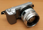
When I cannibalized the parts camera, I took the lens off (probably the only part of that camera which was in decent shape) hoping to one day adapt it for use on a Leica M body or something similar. Well, the lens wound up, like a lot of my projects, kicking around in a drawer for years and just gathering dust. Then the NEX series of cameras came along and with them adapters for every conceivable lens imaginable. Slooowly, eventually, the dim flashbulb in my head went off, I remembered the long forgotten GSN lens and I got to wondering if and how I could pair it with my NEX 5n.

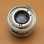
My main issue always came down to how to focus this little beastie. When I had removed the lens from the GSN, along with disabling the shutter and fixing it in the open position, I removed all the of the focusing mechanism and filed down the lens mount flush with the helicoid. (The holes seen were for wires and a metal rod that triggered the shutter inside the lens.)

In hindsight I should have obviously left at least a part of the focusing hardware in place so at this point whatever was going to focus this lens was going to have to be an external thing.

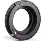
This is where one of my favorite adapters for the NEX series of cameras comes in; Sony E-mount adapters that have a helicoid built in which are meant to allow for close(er) focus with M-mount lenses. These adapters have gotten dramatically cheaper as more Chinese made versions have become available. If you search eBay for “nex helicoid” you will find plenty in the $35-$40 range which is likely the same as the one I have. There is even one that goes for about $18 that can be found by searching for “tinray helicoid”.

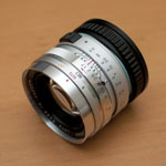
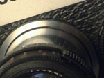
At the moment, and as you can see from the photos, this is in the prototype stages, and I am simply using blu-tack to fix the lens to the adapter. I was actually lucky to have removed as much of the focusing mechanism as I did because in this setup with this particular helicoid adapter infinity focus is very close to spot on. It currently focuses just a little bit past infinity, but I plan to shim that when I do the final mounting.

The only tricky bit has been to tripod mount the camera and check the focus in the corners to ensure that the lens is fairly aligned with the sensor. Of course, this being blu-tack, it is as easy to push and prod the lens in to a rough alignment as it is to knock it right back out. :-/

Eventually, I want to get a Hawks v3 helicoid adapter (much better quality!) for use on my a7R. I will then use some JB Weld on this adapter to permanently fix the GSN lens to the helicoid. I’ll update this page when that happens.

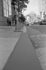
In the meantime, here is a sample shot with the prototype mounted GSN 45mm f/1.7 lens shot at f/5.6 on a Sony NEX 5n (To view the full size 2464×1638 pixel JPG right-click on the image and open it in a new tab.)


Nexstar SE Camera Platform

I recently picked up a used Nexstar 6/8 SE mount and tripod with the idea of using it not only as a grab-and-go for my 72mm f/6 Orion EON (and hopefully a 5 or 6″ SCT OTA down the line) but also in the hopes of using it for some lightweight wide-field long-exposure and time-lapse astrophotography.

I wanted to side-by-side mount a DSLR camera and wide-angle lens combo alongside my unused Celestron 9×50 finderscope from my CPC800 and use an Orion Starshoot autoguider attached to the finder to guide the whole contraption for long exposure photos. That this setup can run on batteries and is lightweight enough to chuck in the back of the car for camping trips made this a really interesting camera platform despite the Nexstar’s well known astrophotography limitations.


Celestron 9×50 Finderscope Autoguider

I found a few pages and forum posts (http://bit.ly/N5GJ7D, http://bit.ly/QoZl9f and http://bit.ly/MUgGDD) with instructions on making an adapter for Orion’s autoguider using PVC pipe fittings but unfortunately all of them required drilling a hole in the finder which I didn’t want to do. I wanted a solution which would require no modifications to the finder and would be easy to undo.

Luckily, while fooling around with the finderscope one afternoon I realized that the threads on the back of Celestron’s 9×50 Model # 51611 finderscope that the cross hair eyepiece attaches to are common 2″ SCT threads! Given that the 1.25″ adapter on the Starshoot autoguider attaches to a standard T-thread on the autoguider body all I needed to find was a male SCT to male T-thread adapter to fit everything together.

I had no clue if such a beast existed and after a little bit of googling I found what I needed at http://agenaastro.com — their Blue Fireball T / T2 Male Thread to SCT Male & M48 was exactly what was needed to make this work. (Seen in the first photo on the right.) This adapter is very low profile and easily allows the finderscope to achieve infinity focus with the Starshoot autoguider.

As shown in the middle and bottom photos on the right, the whole thing comes together in a nice, compact and sturdy assembly and it fits perfectly on the standard Celestron finderscope mount with no modifications needed.

Side-by-Side Camera/Autoguider Mount

Next up was finding a sturdy way to mount the finderscope and camera on the Nexstar.

From a previous project I had a mounting bar with a center hole tapped for a standard 1/4-20 tripod stud with 4 untapped holes on each side. A couple of bolts and washers from the local hardware store worked to mount the Celestron 9×50 finder mount securely to the bar.

To attach the whole thing to the Nexstar, I used the mounting block from the Orion EON 72mm f/6. (Which normally rides piggyback on my CPC800.)

The second photo shows the system all set up with the finderscope, Starshoot autoguider and an IR modified Canon 300D. One of the lenses I plan to use with this setup is a Zenitar 16mm fisheye but unfortunately, the finderscope is mounted so far forward that it projects into the Zenitar’s 180 degree field of view. So I’ll either need to crop the resulting images or figure out some way of mounting the camera further forward or the finderscope further back.

The last image shows everything attached to the Nexstar SE mount and ready to go. Note that I did have to remove the plastic altitude gear covering for the side-by-side mounting to fit which detracts a bit from the looks but everything still works fine.

I love how compact and multi-functional this setup is and can’t wait to get some time out in the field with it. Running with rechargeable batteries for the mount and with spare batteries for the camera and my netbook I think I can get a solid evening of imaging with this setup without ever needing a power plug.

The next step was to adapt a cheap, old wedge for the Nexstar


Rollei 35 TE Repairs

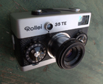
I bought a Rollei 35 TE recently that had a couple of issues and it was driving me bonkers that I could find very little information online about this great camera. Everything I could find, including the service manual, was for the previous generation 35, S and T series cameras.

The issues with my TE were in the meter and lens barrel. The lens barrel was loose and when retracted the lens kept flopping out. (This is common ailment with all Rollei 35 cameras.) The other problem was that the meter would not auto-off after 10 seconds as stated in the manual. It was always on as long as there was a battery in the chamber.

Metering was spot on and agreed perfectly with my Gossen Lunasix3 and the camera still took a great picture despite these issues but they were quickly becoming a major annoyance. Since all the repair estimates I got were for much more than what the camera cost me (and often more that what I could realistically sell it on eBay for) and did not guarantee the meter could be repaired or replaced (in fact most were convinced it could not) I decided to try to fix it myself and document the process for others that might be facing the same issues.

For those doing a repair and in need of extra detail, you can see the full size versions of all the photos in this post by following this link.

Jump Straight to:
 Disasembly / Reassembly
Repairs – Meter Does Not Turn Off
Repairs – Loose Lens Barrel
Easy Battery Solution

Disassembly / Reassembly

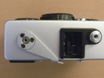
I started with the film advance crank removal as this is usually where I have the most difficulty. In this case the crank cover scew came off without too much force. Underneath it is a small copper washer and the crank itself held in place by three screws as seen in the photo here.

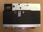
Next there are 2 philips-head screws on either side of the camera and the rest is on the back: the battery lever cap, another flat-topped screw in the middle of the camera and the rewind lever. The rewind lever has a collar underneath the tab as seen in the 2nd photo.

At this point the top cover is not yet ready to be removed as it will not come off without first removing the rewind pin which is held in place by a spring. If you look closely at the rewind pin, you will notice that it has a flat side at half-way between the up and down positions. The pin needs to be turned half-way so the flat side is against the spring so it can be pulled straight out. Use a very small pliers and you may need to use the tip of an x-acto blade to push spring out of the way. Only once pin is removed can the top cover can be pulled off without damage.

In the 3rd photo the top cover has been removed and you can see the rewind pin, the retaining spring and the position the pin needs to be in for removal.

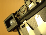
When reassembling the camera, there is trick to getting the pin back in place properly. The rewind pin pushes up a metal rod inside the camera (seen in the final photo) that unlocks the film sprocket (the toothed wheel that the 35mm holes fit in to directly below it) allowing the film to be rewound.

Use small screwdriver to push inner rod up and it will lock in place. This is the only way the rewind pin will fit in back in. The rod will pop back down when you rotate the film sprocket by hand. Try this a couple of times before attempting to put the top cover on. Again, you may need to use the tip of an x-acto bade to push the spring out of the way when reassembling.

Once completed, replace the rewind collar and lever, screw it in place and test it out before finishing reassembly.

Here are a few more detail photos of the camera without the top cover:

Repairs – Meter Does Not Turn Off

This was what led me to do this surgery on the camera in the first place as I found it a real pain having to pop-in, pop-out the battery all the time. A quick test roll showed that the metering was great (I had already checked it against my Gossen Lunasix3) and it could take a great pic, but the auto-off issue was keeping from using the camera effectively.

As soon as I pulled the top cover off I noticed some dry, white powdery gunk under the white wire on the circuit board as seen in the photo here. I scraped it off the circuit board between solder joints with tip of small flat-head screwdriver and happily (amazingly!) the meter immediately started functioning as it should with auto-off after 10 seconds. I figure this was corrosion of some sort that was causing a short and preventing the meter from turning off.

Repairs – Loose Lens Barrel

This was the only issue that I could find any information about online as apparently affects a lot of Rollei 35’s. Unfortunately, the fix requires breaking down the camera even further to replace a friction collar inside the camera body and I really didn’t want to go to those lengths as all those mechanical bits looked like a little more than I knew how to deal with.

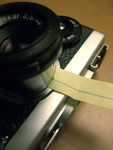
Instead I had the idea of going in through the front of the camera between the lens barrel and the collar that holds it in place. Whatever I used needed to be adhesive on one side so it could stick to the inside of the lens collar and stay in place. I tried some flocking paper left over from another project but it was way too thick and after a little experimenting discovered that a simple yellow Post-It was the perfect solution — it was just the right thickness and the adhesive was not too so strong as to make it difficult to work with.

I cut off the the adhesive strip from a fresh Post-It and trimmed it so it was about 1.5cm wide. With the camera fully assembled and the lens locked in place, I slid the Post-It between the lens barrel and collar with adhesive side outward against the lens collar and worked it into the camera af far as it would go. This should only be about 2-4mm. I found the best place on my Rollei was at about the 2 o’clock position of the lens barrel. Once the Post-It was in postion, I folded it down against the body of the camera, unlocked the lens and slid it in and out to test if the friction was enough to hold the lens and if the paper would stay in place. Once I was satisfied with the positioning, I used an x-acto knife to trim off the excess paper and then a black sharpie to paint over yellow Post-It color.

This method worked perfectly for me producing exactly the right friction to hold the lens and is still in place showing no signs of causing any other issues. Also, once touched up with a black sharpie, you can’t see it unless you really look…

Easy Battery Solution

The best, cheapest battery tip I have found for the Rollei 35 TE and SE cameras came from this flickr discussion [Thank you nadameansnothing!]:

http://www.flickr.com/groups/rollei35/discuss/72157622459831809/

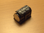
Basically, the idea is to use three LR44 batteries and one LR43 battery wrapped in electrical tape to hold them together. With the thinner LR43 in the set the length is perfect and you can wrap enough tape around them to increase the diameter until you get a snug fit in the holder. (I didn’t bother and it works fine.) Best of all, these batteries are easy to find, comparatively cheap and they last forever.

All together they produce 6V but the TE / SE meters don’t seem to mind the slight over-voltage as much as the previous generation meters did. So it’s not strictly necessary, but you can use a single depleted cell in the set to get closer to the camera’s native 5.6V. I haven’t really noticed a difference either way.


Yashica Electro 35 GSN Rangefinder Replacement

My first attempt at finding a working copy of one of these fabulous but mechanically and electronically finicky cameras landed me a fine looking example of electronics that were way beyond repair. Still, the $30 price of admission was well worth the entertainment value of trying to fix it up. 🙂

The second attempt was an eBay buy that was maybe a 9.5 cosmetically and sound mechanically but had one major flaw which made it a pain to use… The rangefinder spot in the viewer that is used to focus was almost non-existent. It had just the barest ghost of an overlapping image which made focusing difficult even on bright days.

Since I had the parts from a whole other camera, (happily the focusing mechanism on the broken GSN was in stellar shape) I decided it was high time to perform a little surgery and build… a Frankie.

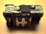
You can see in the photo on the right just how bad shape the old rangefinder mechanism was in… The top one was the mechanism I replaced and you can see how the diagonal piece of glass there is nearly transparent. This gold coated piece of glass is basically a beam splitter that superimposes the focusing area on the view through the lens. With the coating nearly gone as in the top photo, very little was being reflected and consequently the focusing area had pretty much disappeared.

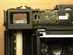
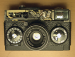
There are other sites with instructions on disassembly of the GSN so I won’t go too much in to that here. This photo shows the camera with the top-plate already removed and the rangefinder mechanism exposed. The screws circled in green hold the whole unit in place and are all that need to be removed. When removing it, lift out the left side first (where the film rewind crank is) and be careful of the Over / Under lights and other electronics on the right.

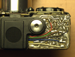
When replacing the rangefinder mechanism, tuck the right side under the electronics and it should just drop in to place. Don’t screw it down yet, as you will need to make sure the focusing lever is set in the lens tab in the next step. Note the location of the vertical focus adjustment screw circled in the photo on the right.

This photo shows the metal tab that keeps the lens indexed with the rangefinder mechanism. Underneath the rangefinder mechanism is a focusing lever that moves the mirror assembly back and forth. This lever needs to rest in a tab that is attached to the lens. (Both are circled in the picture.) Once this is set, move the lens from close to far focus and back a few times to make sure no wiries are obstucting the movement or worse, getting pinched somehwhere in the process.After this step, you can screw the rangefinder mechanism in place and proceed with the final adjustments.

The final and most complicated step is adjusting focus so the lens is in register with the rangefinder mechanism. The method I found easiest was to set the lens to infinity and then adjust the rangefinder to that.

To adjust the rangefinder, there are 2 screws that control horizontal and vertical registration of the focusing square. The photo on the right shows the location of the horizonal 45° adjustment screw. [It was pointed out to me (thanks Alfredo!) that the horizontal adjustment is the cross-like screw located next to the moveable rangefinder lens, labelled as “infinity adjustment” on page 36 of the GSN service manual.] The vertical adjustment screw is shown two photos back. I was lucky and actually didn’t have to touch the verical registration at all.

Mount the camera on a tripod and point the it at a distant object. I actually found it easier to do this step at night with the camera trained on a street light in the distance. Set the lens to infinity marking – it should be right against the stop and not go any further. When you look through the viewfinder you’ll see whatever object you’ve trained on is “out of focus.” Just adjust the horizontal (and verical if needed) until the images register exactly. Go back and verify that the lens is still set to infinity and check focus again.

Before putting a roll of film in the camera I wanted to be reasonably sure that focus was good.

To do so, I used an old roll of film that I accidentally fixed but didn’t develop (Oops! A couple of pieces of electrical tape would have worked just as well though…) to hold in place a square of material I cut from a soft CD sleeve.

I like the CD sleeve material for this as it is cheap, lint-free and the thinness and perforations make it easy to tell where focus is. A good alternative would be tracing or rice paper but this is what I had on hand and it worked well for me. Basically, the thinner the better…

Here you can see what it looks like focusing on a desk-lamp at closest-focus on the GSN which is about 80 cm (or 2.5 ft). Looking through the viewfinder and looking at the back of the camera, the focus seemed to match well and focusing at a distant street light with the lens set to infinity showed an equally sharp image.

This is not meant to be a definitive test of focus, just a quick preview before putting everything back together in case something is really off… A true test of focus can only really come from a test roll. (At least with the gear I have on hand!)

This should be it! To keep focus from slipping, brush some clear nail polish on the adjustment screws and let it dry before assembling the camera.

The surgery worked! My GSN is still in focus and the “new” focusing mechanisim is an astounding improvement.

When putting the camera back together I used the newest looking bits from both and now the camera looks great along with working great.

It’s also nice to know I have parts to replace nearly anything on this camera should anything else ever break…

Here are a few links to sites and manuals that were very helpful in figuring all this stuff out:


Here are a couple of shots from my GSN set on flicker:

House of Shields

wet paint


StarlightXpress MX7C to MX716 Conversion

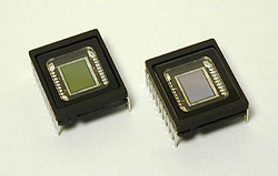
Sony ICX249AK (color) and ICX249AL (mono)

Shortly after I bought my MX7C I read that the hardware in the MX5C and MX516 were the same and all that needed to be substituted was the CCD chip. I contacted Terry Platt of StarlightXpress and asked if this was the same for the MX7C line of cameras. Happily this was the case and I put in an order for a Sony ICX249AL CCD chip directly to StarlightXpress.

Now why bother with a mono chip? Why the heck did I buy a color camera in the 1st place? Well, the convenience of 1 shot color is still a huge plus for me but the possibility of having a mono chip capable of taking more sensitive higher resolution luminance images to combine with color data was intriguing. Not having to buy another camera to be able to do this was what sold me though…

If you’re not squeamish about this sort of surgery, the swap is not hard to do and a fairly painless calibration is all you need to do to be up and running. However, I’ll insert the standard disclaimer here: This sort of thing voids your warranty. If you’re not comfortable or don’t know what you’re doing, try and arrange for the camera to be sent back to StarlightXpress or a local distributor and they will most likely do this for you. I have no affiliation with StarlightXpress nor is the information in this article endorsed by them in any way. Its something I did myself and wanted to document in case others out there were interested in doing the same.

The calibration instructions described here are adapted from a document provided by Michael Hattey of StarlightXpress. For the more technically inclined, you can download PDF spec sheets with very detailed information on these chips here Sony ICX249AK (Color) and here Sony ICX249AL (Mono). Note: I now have these spec sheets on my site instead of Sony, as they kee changing the links on me. Therefore there is a chance that they may be out of date. If you’re looking for up to the second info on these chips, please check Sony’s site at: http://products.sel.sony.com/semi/

First lets take a look at opening the camera.

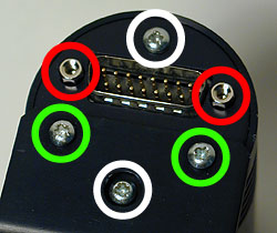
The picture to the right is confusing but there is method to the madness.

The view is of the rear of the camera. The 2 screws circled in green only hold the tripod adapter in place.

The screws circled in white attach the back plate to 2 long bolts that run the length of the camera that hold the optical window housing in place. These must be removed. (Be careful not to over tighten these when you put the camera back together!)

The hexagonal nuts circled in red hold the back plate of the camera to the 15 pin plug that is soldered to the circuit board. These must be also be removed.

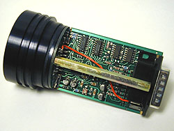
Once the back plate and the camera housing have been removed you will notice a long brass bolt on each side of the camera.

These bolts hold the front part of the camera in place – the metal housing for the CCD to which the optical window is attached.

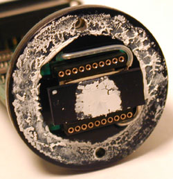
Be careful when removing these as the whole front of the camera will come off and the CCD enclosure is made airtight with

thermal heat sink grease as you can see in the picture on the bottom right. If you are going to do this it would be a good idea to get some computer silicone heat sink paste (a.k.a. thermal grease). at RadioShack or on-line.

The grease under the chip on my camera was completely dry and I had to clean it and reapply some. Remember though that a little goes a long way with this stuff!

While you’re at Radio Shack pick up an antistatic bracelet. CCD chips (like most electronics) can be easily destroyed by a static discharge and it is always good practice to keep yourself grounded.

Here is a close up of the chip. The easiest way to remove it is with a thin flathead screwdriver like in the image or prying it up with an x-acto blade. Alternatively, places like RadioShack have specific tools for inserting and removing chips from sockets without damaging the pins.

The trick is to gently lift one end and then the other off of the cold finger until the chip comes loose. It is very easy to bend the pins if you aren’t careful.

Note the notch on the left side of the chip. This is not pin 1. (It is in fact close to pin 10) It is there, I assume, for leverage to make removing the chip from a socket easier. Pin 1 on these chips is marked by a circular indentation on the underside of the CCD.

Since the notch is easily visible I used it to mark the orientation of the chip in the socket. This is very important to take note of. If the CCD chip is incorrectly inserted you could destroy the CCD and possibly the camera. That said though, the Sony CCD chips are very similar and pin 1 (or 10) should be easy to identify.

I used a drop of liquid paper to mark the position of pin 10 on the cold finger for future reference.

In the bottom picture you see the cold finger with the CCD removed and dried grease I had to replace. The grease around the edge of the camera was thick but holding out so I left it. It is there to make the enclosure airtight and prevent moisture condensing and then freezing on the CCD chip as it cools down. This was a major problem I had with my CB245.

Installation of the new chip is easy – correctly orient the CCD in the socket, check that all the pins are entering the sockets correctly and press down gently and evenly putting pressure over the pins on each side. Its should just slide in…

This image shows the CCD mounting as seen edge on with the new chip installed. Under the CCD is the cold finger and under that is the TEC or Thermoelectric Cooling Device.

Once the new chip is installed replace the CCD housing and secure it with the long brass bolts. Do yourself a favor and make sure that the glass is very clean both on the housing and on the CCD window before closing it. Any dust specs on these surfaces will show up as circles or doughnuts (depending on your telescope) when you try to image forcing you to take flat field frames.

Don’t close the rest of the camera yet as we now have to calibrate it for the new chip. For calibration we will run a few tests with the camera open and running so adjustments can be made to 2 variable resistors located on opposite sides of the printed circuit board.

VR1 is located close to the center of the PCB and is pictured on the right. Click on the image for a close up.

First of all fire up the camera and take a test image through a pinhole or with a camera lens attached. Hopefully you’ll get a normal image and we can move on to dark frame adjustment.

If there is a problem, power off the camera and double check the obvious. If the problem persists try reinstalling the color chip and taking an image with that.

VR1 - Variable Resistor 1 (click for close up)

For the dark frame test we need to let the camera cool down for about 5 minutes. The cover the camera so no light can make it to the CCD chip (Remember how sensitive these chips are to light! I actually put my camera in a black cloth bag as well as covering the CCD.) and take a 1 second exposure and look at the histogram of the dark frame you just took.

The histogram of a properly calibrated camera should look a lot like the one on the above. (Note: I used the MX716 version of the software – StarlightXpress Star_MX7 v2.0e (04/06/2002)) There should no more than 1 or 2 entries in the VAL field and the values should range between 006 and 016. If the values are greater than 16, use a small flathead screwdriver to turn VR1 a few degrees anti-clockwise. Then take another 1 second dark frame and examine the histogram values to see if further adjustment is needed. If the values are lower than 6, use a small flathead screwdriver to turn VR1 a few degrees clockwise and repeat the dark frame histogram process until the values are correct.

After this process is complete it is a good idea to take a 5 minute dark frame to make sure the darks are free of hot spots bright streaks. There will probably be a brighter area in the upper left area of the frame. This is caused by the output amplifier and should be quite faint. If you have the chance it would be a good idea to compare your dark to the dark frame of a calibrated camera of the same type.

For the calibration of VR2 we are going to need a light with a narrow a beam as possible to simulate a star. There are 2 methods for doing this – one easy way is to shine a light or a laser at a spherical Christmas tree ornament to at a ball bearing and to focus the CCD and camera lens or telescope at the reflected beam.

The method I used was to tape a high power eyepiece to a flash light as seen in the image on the right. The eyepiece will focus (or narrow) the beam of light to a finer point. I used a University Optics 12.5mm Orthoscopic. I found the beam to be too bright even with the flashlight on the lowest setting so I added a variable polarizing moon filter to dim the light even more.

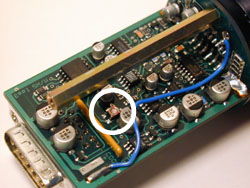
VR2 is located on the opposite side of the PCB towards the edge and front of the camera as seen in the picture on the right. This variable resistor controls the ABG (Anti-Blooming Gate) bias on the CCD chip. Anti-blooming prevents streaking and bloating of bright stars but slightly and affects linearity. ABG can be effectively turned off by turning this VR about 20° anti-clockwise.

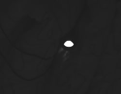
To calibrate VR2 we need to focus the camera on a light source (as previously described) in a dark room and take a 1 second integration. My camera’s ABG bias was set too low and my image of the light source looked a like the image on the right. Instead of being as close to a point of light as possible, I got an oval due to “bleeding” caused by anti-blooming being almost set to the off position.

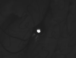
To calibrate the camera take a 1 second picture of your light source. If the resulting image looks like the middle picture on the right and/or if there is a bright streak in the image then the ABG gate is set too low. Turn VR2 a few degrees clockwise and take another integration.

If the image is gray or grainy then the ABG is set too high. Turn VR2 a few degrees anti-clockwise and take another integration to test the result. If you overshoot too much in the clockwise direction the camera sensitivity will be decreased by too much anti-blooming. If you overshoot anti-clockwise sensitivity will be higher but stars will be bloated and oval and streaks will appear so proper calibration is critical. This is the hardest and most painstaking part of the calibration to get right. My suggestion is to turn VR2 anti-clockwise until you get a bloated star image like mine and then take 1 second integrations turning VR2 clockwise 2 or 3 degrees at a time until the blooming just disappears.

VR2 - Variable Resistor 2 (click for close up)

For the final step in calibrating the camera point it at a white target and take an integration that results in a mostly saturated image. Here I printed a 4 colored boxes and a thin crosshair for reference. The resulting histogram should have a major peak at a VAL of 255.

If the peak does not reach a VAL of 255 or if the image look gray or grainy then VR2 is set too far clockwise and you must go back and adjust it.

And that is it! You now have a MX7 with either the color or the mono chip installed, calibrated and ready to go!

Check my gallery to see images taken with both the MX7 and MX716:

http://astroturtle.com/imaging/

Comments Off on StarlightXpress MX7C to MX716 Conversion more...

Copyright © 1996-2010 astroturtle. All rights reserved.
Jarrah theme by Templates Next | Powered by WordPress