Tag: repair

Atari 400 repair and composite video mod


I recorded a set of videos recently documenting some troubleshooting of an ATARI 400 system, and the conversion from RF to composite video. There was so little info out there about this mod that I thought even my crummy video would help. 

The embedded video above is the 4th and final part that shows the composite conversion. Here are links to the other parts and some docs and forum posts I found along the way… 

Part 1: https://youtu.be/mojxsA4EAFQ
Part 2: https://youtu.be/9mvjiq9HEIk
Part 3: https://youtu.be/qBcRygpFbtI

Atari 400/800 Service Manual:
http://www.jsobola.atari8.info/dereat…

S-Video to Composite info:
https://www.epanorama.net/circuits/sv…

Atari 400 video mod info:
https://atariage.com/forums/topic/178…
https://atariage.com/forums/topic/209…


Rollei 35 TE Repairs

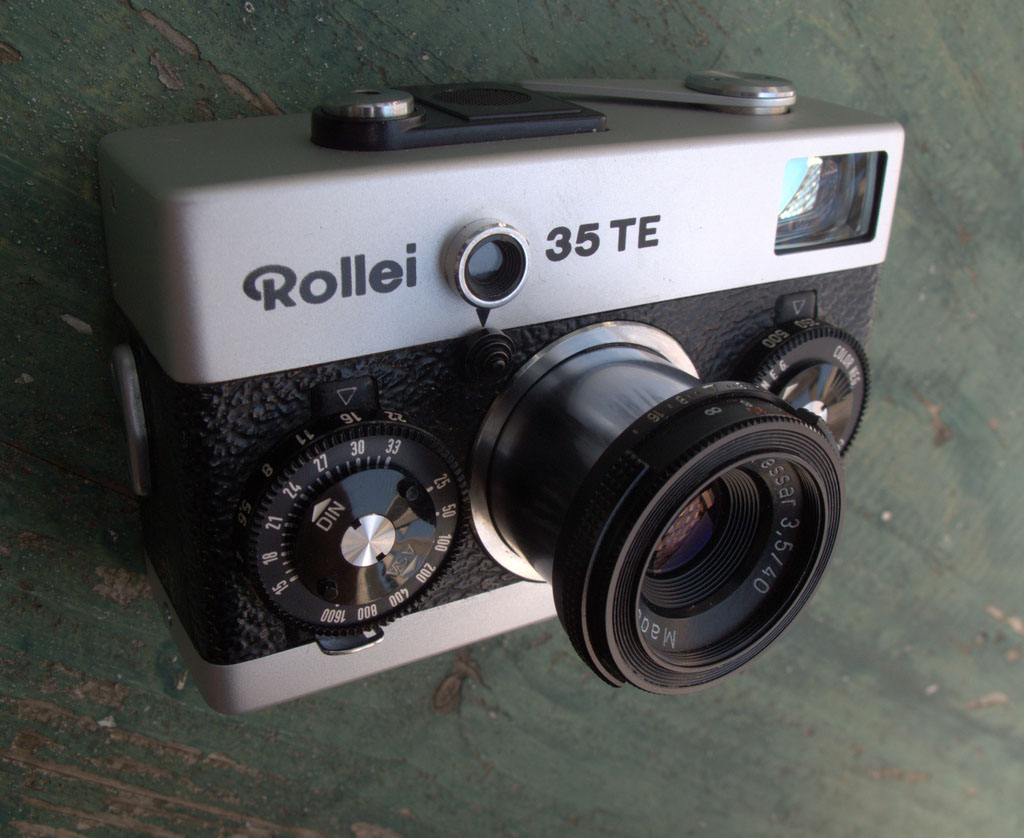
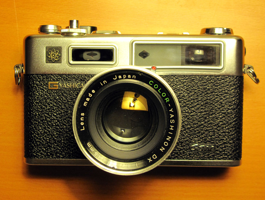
I bought a Rollei 35 TE recently that had a couple of issues and it was driving me bonkers that I could find very little information online about this great camera. Everything I could find, including the service manual, was for the previous generation 35, S and T series cameras.

The issues with my TE were in the meter and lens barrel. The lens barrel was loose and when retracted the lens kept flopping out. (This is common ailment with all Rollei 35 cameras.) The other problem was that the meter would not auto-off after 10 seconds as stated in the manual. It was always on as long as there was a battery in the chamber.

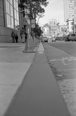
Metering was spot on and agreed perfectly with my Gossen Lunasix3 and the camera still took a great picture despite these issues but they were quickly becoming a major annoyance. Since all the repair estimates I got were for much more than what the camera cost me (and often more that what I could realistically sell it on eBay for) and did not guarantee the meter could be repaired or replaced (in fact most were convinced it could not) I decided to try to fix it myself and document the process for others that might be facing the same issues.

For those doing a repair and in need of extra detail, you can see the full size versions of all the photos in this post by following this link.
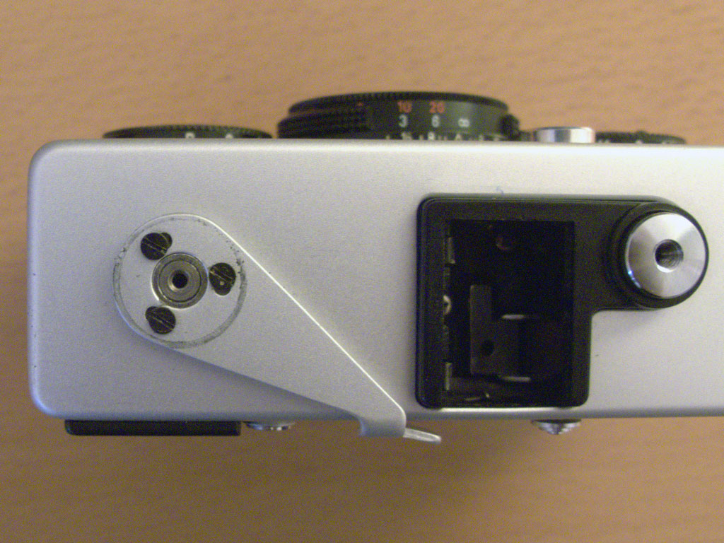
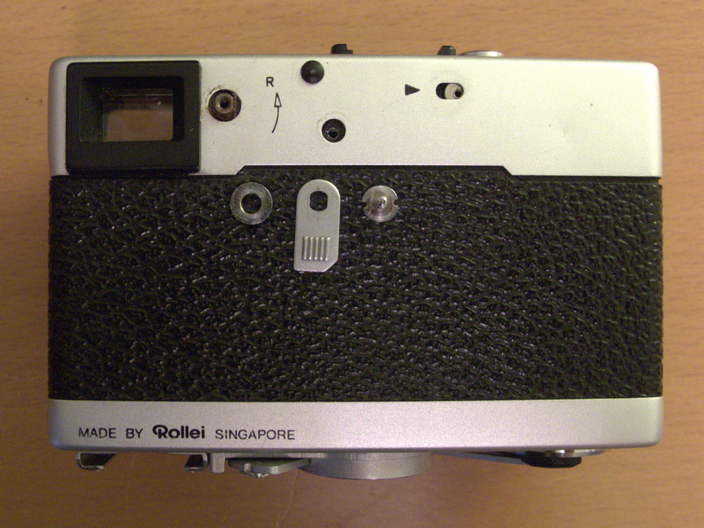
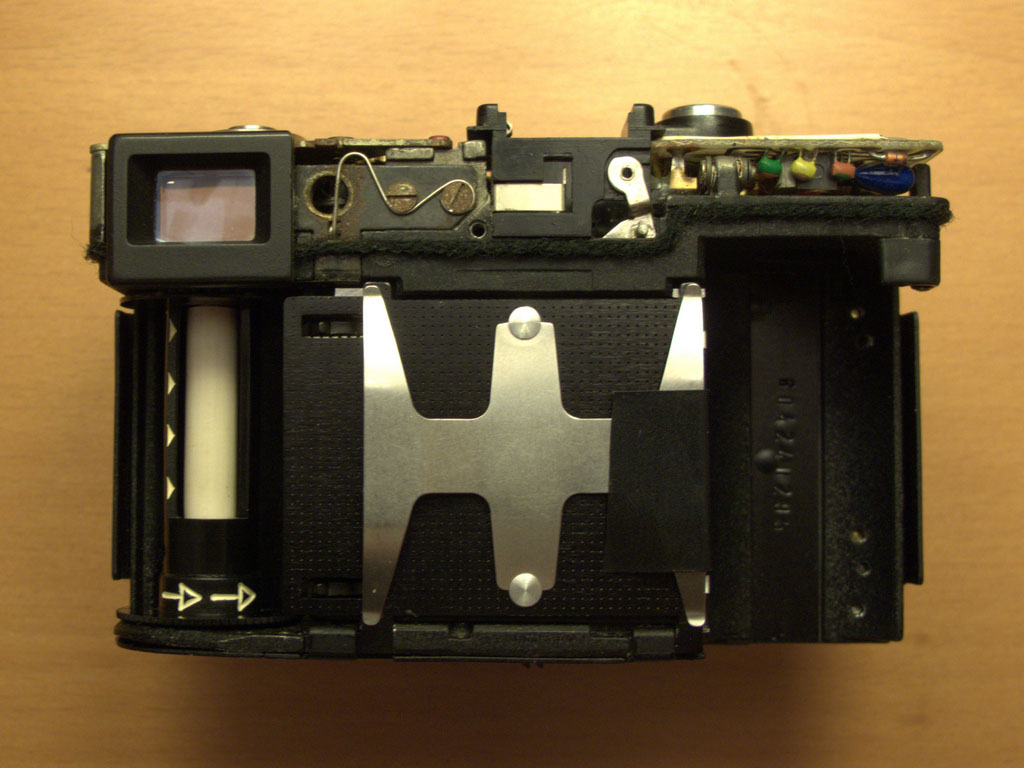
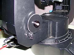
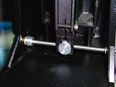
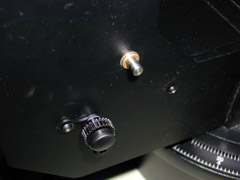
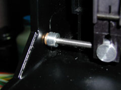
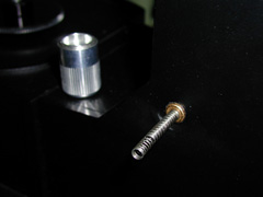
Jump Straight to:
 Disasembly / Reassembly
Repairs – Meter Does Not Turn Off
Repairs – Loose Lens Barrel
Easy Battery Solution

Disassembly / Reassembly

I started with the film advance crank removal as this is usually where I have the most difficulty. In this case the crank cover scew came off without too much force. Underneath it is a small copper washer and the crank itself held in place by three screws as seen in the photo here.

Next there are 2 philips-head screws on either side of the camera and the rest is on the back: the battery lever cap, another flat-topped screw in the middle of the camera and the rewind lever. The rewind lever has a collar underneath the tab as seen in the 2nd photo.

At this point the top cover is not yet ready to be removed as it will not come off without first removing the rewind pin which is held in place by a spring. If you look closely at the rewind pin, you will notice that it has a flat side at half-way between the up and down positions. The pin needs to be turned half-way so the flat side is against the spring so it can be pulled straight out. Use a very small pliers and you may need to use the tip of an x-acto blade to push spring out of the way. Only once pin is removed can the top cover can be pulled off without damage.

In the 3rd photo the top cover has been removed and you can see the rewind pin, the retaining spring and the position the pin needs to be in for removal.

When reassembling the camera, there is trick to getting the pin back in place properly. The rewind pin pushes up a metal rod inside the camera (seen in the final photo) that unlocks the film sprocket (the toothed wheel that the 35mm holes fit in to directly below it) allowing the film to be rewound.

Use small screwdriver to push inner rod up and it will lock in place. This is the only way the rewind pin will fit in back in. The rod will pop back down when you rotate the film sprocket by hand. Try this a couple of times before attempting to put the top cover on. Again, you may need to use the tip of an x-acto bade to push the spring out of the way when reassembling.

Once completed, replace the rewind collar and lever, screw it in place and test it out before finishing reassembly.

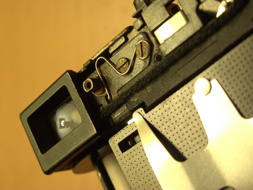
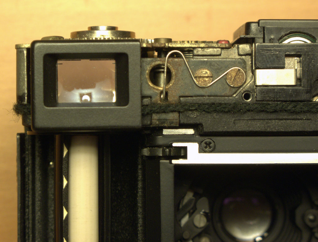
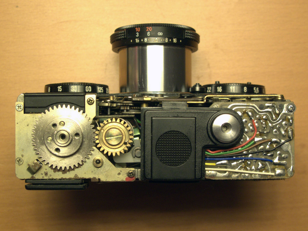
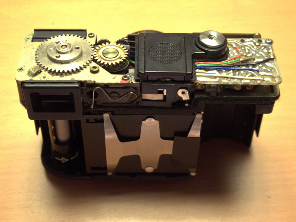
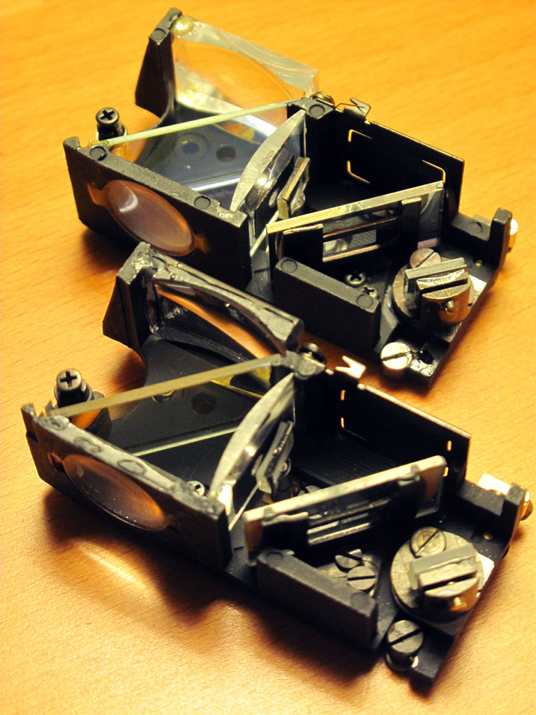
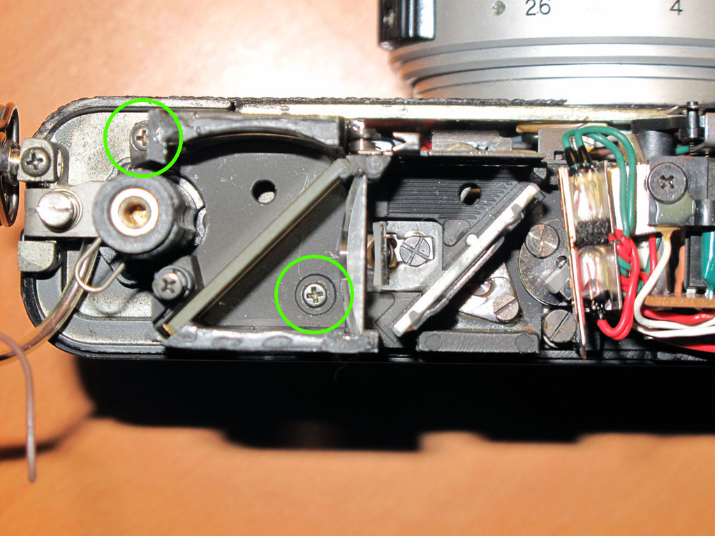
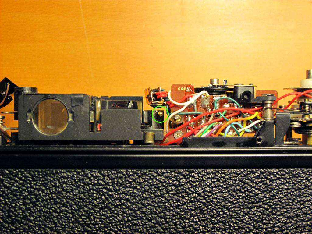
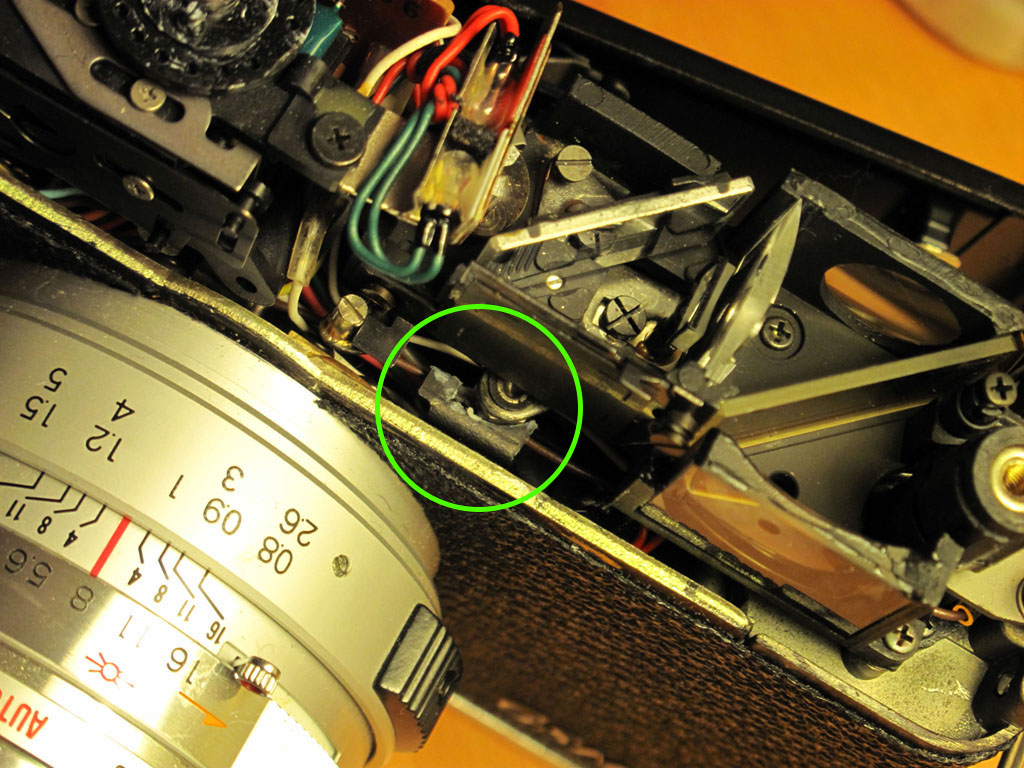
Here are a few more detail photos of the camera without the top cover:
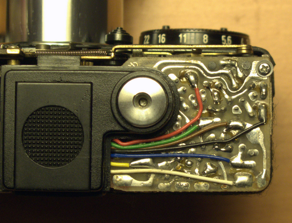
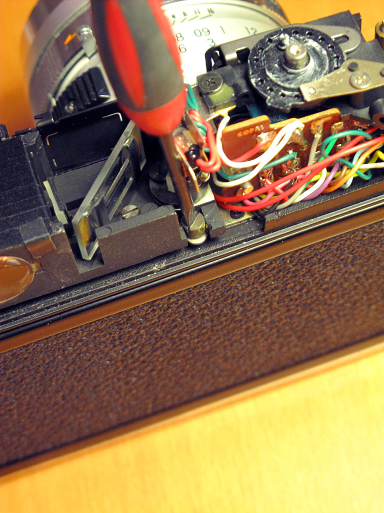
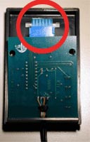
Repairs – Meter Does Not Turn Off

This was what led me to do this surgery on the camera in the first place as I found it a real pain having to pop-in, pop-out the battery all the time. A quick test roll showed that the metering was great (I had already checked it against my Gossen Lunasix3) and it could take a great pic, but the auto-off issue was keeping from using the camera effectively.

As soon as I pulled the top cover off I noticed some dry, white powdery gunk under the white wire on the circuit board as seen in the photo here. I scraped it off the circuit board between solder joints with tip of small flat-head screwdriver and happily (amazingly!) the meter immediately started functioning as it should with auto-off after 10 seconds. I figure this was corrosion of some sort that was causing a short and preventing the meter from turning off.

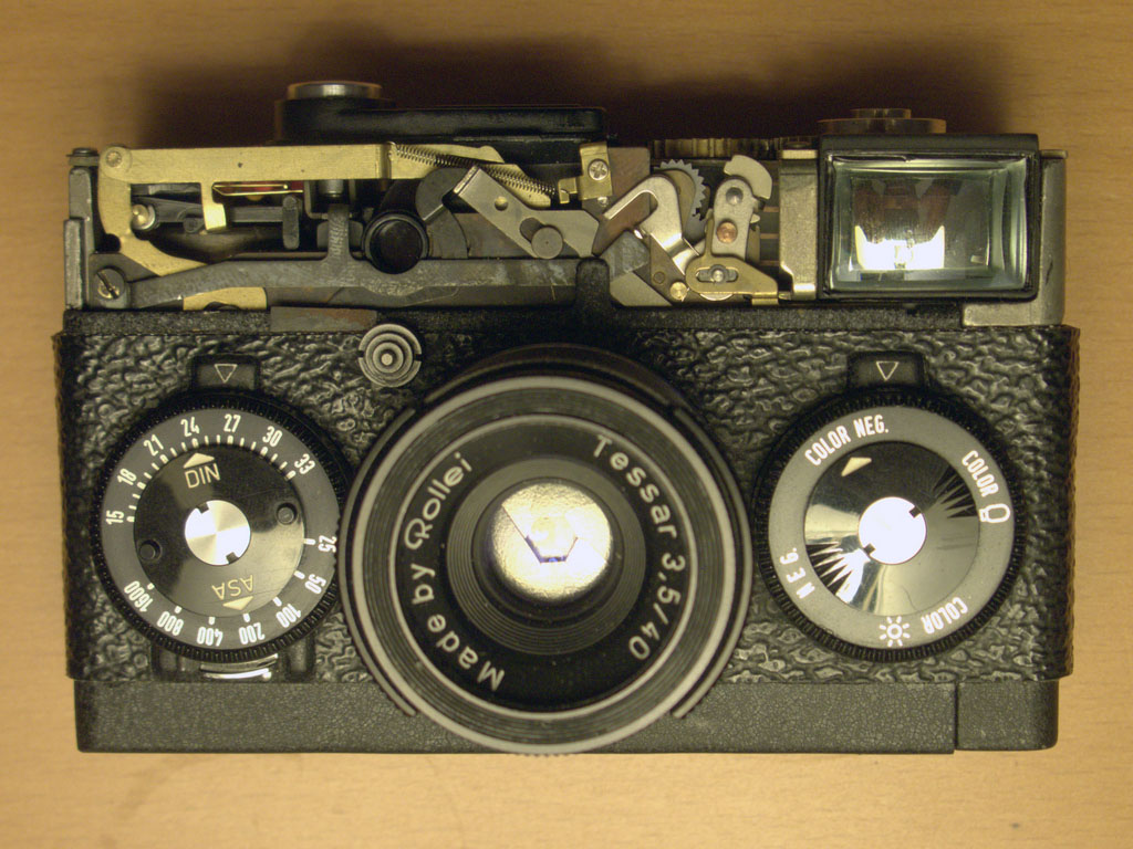
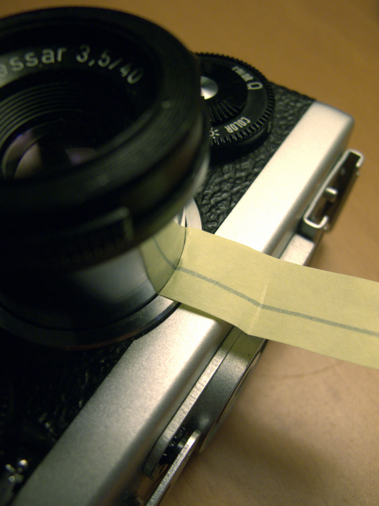
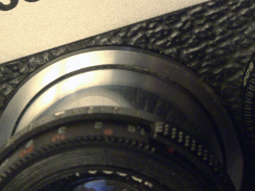
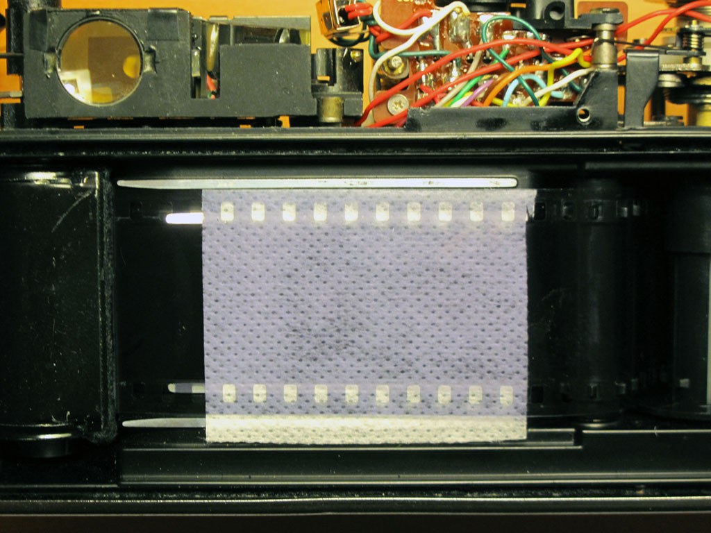
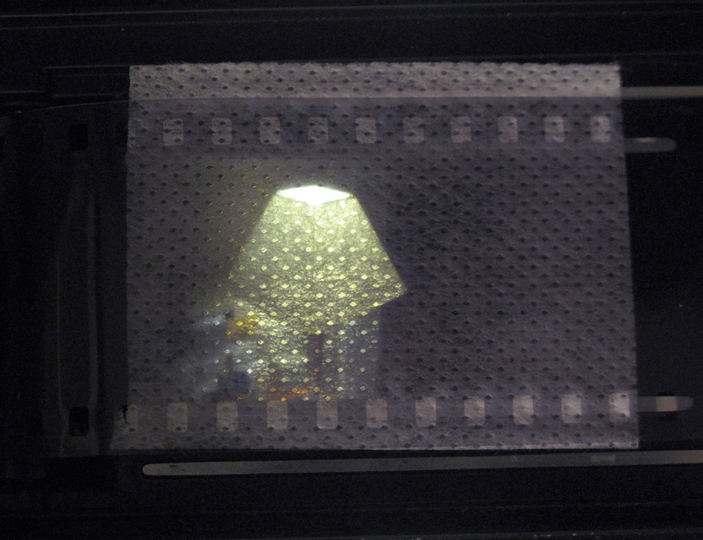
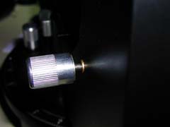
Repairs – Loose Lens Barrel

This was the only issue that I could find any information about online as apparently affects a lot of Rollei 35’s. Unfortunately, the fix requires breaking down the camera even further to replace a friction collar inside the camera body and I really didn’t want to go to those lengths as all those mechanical bits looked like a little more than I knew how to deal with.

Instead I had the idea of going in through the front of the camera between the lens barrel and the collar that holds it in place. Whatever I used needed to be adhesive on one side so it could stick to the inside of the lens collar and stay in place. I tried some flocking paper left over from another project but it was way too thick and after a little experimenting discovered that a simple yellow Post-It was the perfect solution — it was just the right thickness and the adhesive was not too so strong as to make it difficult to work with.

I cut off the the adhesive strip from a fresh Post-It and trimmed it so it was about 1.5cm wide. With the camera fully assembled and the lens locked in place, I slid the Post-It between the lens barrel and collar with adhesive side outward against the lens collar and worked it into the camera af far as it would go. This should only be about 2-4mm. I found the best place on my Rollei was at about the 2 o’clock position of the lens barrel. Once the Post-It was in postion, I folded it down against the body of the camera, unlocked the lens and slid it in and out to test if the friction was enough to hold the lens and if the paper would stay in place. Once I was satisfied with the positioning, I used an x-acto knife to trim off the excess paper and then a black sharpie to paint over yellow Post-It color.

This method worked perfectly for me producing exactly the right friction to hold the lens and is still in place showing no signs of causing any other issues. Also, once touched up with a black sharpie, you can’t see it unless you really look…

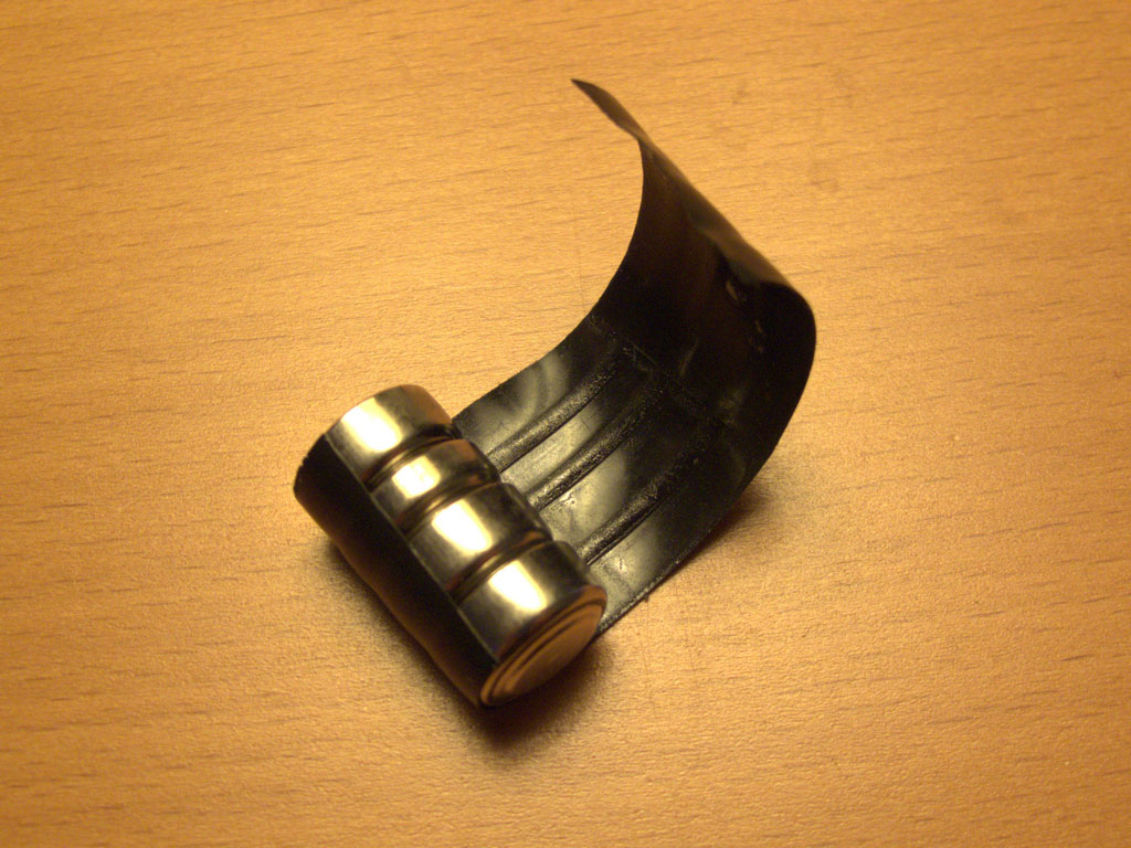
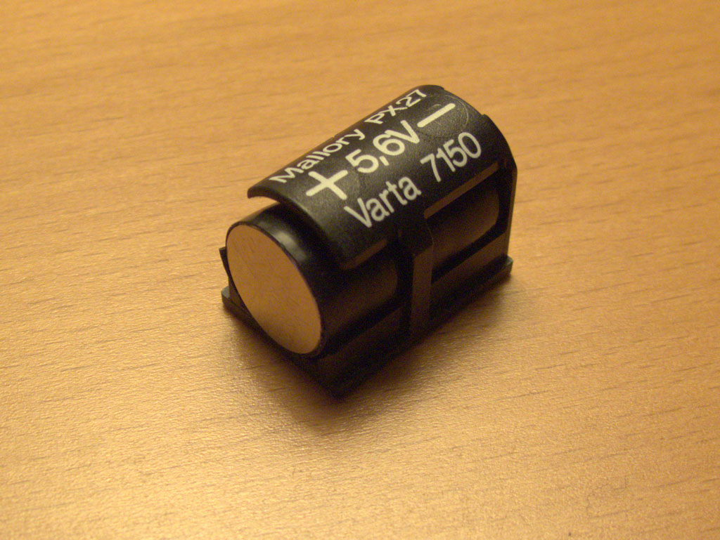
Easy Battery Solution

The best, cheapest battery tip I have found for the Rollei 35 TE and SE cameras came from this flickr discussion [Thank you nadameansnothing!]:

http://www.flickr.com/groups/rollei35/discuss/72157622459831809/

Basically, the idea is to use three LR44 batteries and one LR43 battery wrapped in electrical tape to hold them together. With the thinner LR43 in the set the length is perfect and you can wrap enough tape around them to increase the diameter until you get a snug fit in the holder. (I didn’t bother and it works fine.) Best of all, these batteries are easy to find, comparatively cheap and they last forever.

All together they produce 6V but the TE / SE meters don’t seem to mind the slight over-voltage as much as the previous generation meters did. So it’s not strictly necessary, but you can use a single depleted cell in the set to get closer to the camera’s native 5.6V. I haven’t really noticed a difference either way.


Yashica Electro 35 GSN Rangefinder Replacement

My first attempt at finding a working copy of one of these fabulous but mechanically and electronically finicky cameras landed me a fine looking example of electronics that were way beyond repair. Still, the $30 price of admission was well worth the entertainment value of trying to fix it up. 🙂

The second attempt was an eBay buy that was maybe a 9.5 cosmetically and sound mechanically but had one major flaw which made it a pain to use… The rangefinder spot in the viewer that is used to focus was almost non-existent. It had just the barest ghost of an overlapping image which made focusing difficult even on bright days.

Since I had the parts from a whole other camera, (happily the focusing mechanism on the broken GSN was in stellar shape) I decided it was high time to perform a little surgery and build… a Frankie.

You can see in the photo on the right just how bad shape the old rangefinder mechanism was in… The top one was the mechanism I replaced and you can see how the diagonal piece of glass there is nearly transparent. This gold coated piece of glass is basically a beam splitter that superimposes the focusing area on the view through the lens. With the coating nearly gone as in the top photo, very little was being reflected and consequently the focusing area had pretty much disappeared.

There are other sites with instructions on disassembly of the GSN so I won’t go too much in to that here. This photo shows the camera with the top-plate already removed and the rangefinder mechanism exposed. The screws circled in green hold the whole unit in place and are all that need to be removed. When removing it, lift out the left side first (where the film rewind crank is) and be careful of the Over / Under lights and other electronics on the right.

When replacing the rangefinder mechanism, tuck the right side under the electronics and it should just drop in to place. Don’t screw it down yet, as you will need to make sure the focusing lever is set in the lens tab in the next step. Note the location of the vertical focus adjustment screw circled in the photo on the right.

This photo shows the metal tab that keeps the lens indexed with the rangefinder mechanism. Underneath the rangefinder mechanism is a focusing lever that moves the mirror assembly back and forth. This lever needs to rest in a tab that is attached to the lens. (Both are circled in the picture.) Once this is set, move the lens from close to far focus and back a few times to make sure no wiries are obstucting the movement or worse, getting pinched somehwhere in the process.After this step, you can screw the rangefinder mechanism in place and proceed with the final adjustments.

The final and most complicated step is adjusting focus so the lens is in register with the rangefinder mechanism. The method I found easiest was to set the lens to infinity and then adjust the rangefinder to that.

To adjust the rangefinder, there are 2 screws that control horizontal and vertical registration of the focusing square. The photo on the right shows the location of the horizonal 45° adjustment screw. [It was pointed out to me (thanks Alfredo!) that the horizontal adjustment is the cross-like screw located next to the moveable rangefinder lens, labelled as “infinity adjustment” on page 36 of the GSN service manual.] The vertical adjustment screw is shown two photos back. I was lucky and actually didn’t have to touch the verical registration at all.

Mount the camera on a tripod and point the it at a distant object. I actually found it easier to do this step at night with the camera trained on a street light in the distance. Set the lens to infinity marking – it should be right against the stop and not go any further. When you look through the viewfinder you’ll see whatever object you’ve trained on is “out of focus.” Just adjust the horizontal (and verical if needed) until the images register exactly. Go back and verify that the lens is still set to infinity and check focus again.

Before putting a roll of film in the camera I wanted to be reasonably sure that focus was good.

To do so, I used an old roll of film that I accidentally fixed but didn’t develop (Oops! A couple of pieces of electrical tape would have worked just as well though…) to hold in place a square of material I cut from a soft CD sleeve.

I like the CD sleeve material for this as it is cheap, lint-free and the thinness and perforations make it easy to tell where focus is. A good alternative would be tracing or rice paper but this is what I had on hand and it worked well for me. Basically, the thinner the better…

Here you can see what it looks like focusing on a desk-lamp at closest-focus on the GSN which is about 80 cm (or 2.5 ft). Looking through the viewfinder and looking at the back of the camera, the focus seemed to match well and focusing at a distant street light with the lens set to infinity showed an equally sharp image.

This is not meant to be a definitive test of focus, just a quick preview before putting everything back together in case something is really off… A true test of focus can only really come from a test roll. (At least with the gear I have on hand!)

This should be it! To keep focus from slipping, brush some clear nail polish on the adjustment screws and let it dry before assembling the camera.

The surgery worked! My GSN is still in focus and the “new” focusing mechanisim is an astounding improvement.

When putting the camera back together I used the newest looking bits from both and now the camera looks great along with working great.

It’s also nice to know I have parts to replace nearly anything on this camera should anything else ever break…

Here are a few links to sites and manuals that were very helpful in figuring all this stuff out:


Here are a couple of shots from my GSN set on flicker:

House of Shields

wet paint


Meade LX50 DEC Axis Issues

Hoo boy, did I have a sick DEC axis. l think I only started noticing it when I started guiding long-exposure shots as it was on the most part livable for the visual stuff.

I had a few problems:

  1. Reversing direction quickly back and forth several times would actually “crash” the LX50! The power led would start blinking and all I could do was power off, wait a few seconds and power on to get it to respond. Kinda’ like an operating system or two that I won’t mention here! ;o)
  2. Speed of motion on the DEC axis had nothing to do with the RA axis. Either it was Speedy Gonzalez or the motor would actually come to a grinding (seriously – grinding) halt.
  3. When I reversed direction it would take a long time before whatever was in the FOV actually moved. It was like slack was being picked up somewhere in the tangent arm.

None of this is very good when you’re trying to guide a photo on a $%&# guide star you can barely see and I won’t even go into what an autoguider will try to do…

Problem 1 was the easiest to solve. It was pretty obviously power related but after trying fresh batteries, NiCads, even a blasted 9v the “blinking light” weirdness persisted. After some good advice (always!) from the folks at SCT-User I decided to give it a go with a little 12v, 1A power brick. That did the trick and I’ve never had any problems since. Seems the problem is
related to current and how much current batteries can sustain. Phil Chambers explained what was going on much better than I ever could in a post to the SCT-Users group:

“The issue, as Rod said, is the gearing which loads the motor down. What is probably happening is the motor is loaded, its cold so it moves a little harder so the motor needs more current but as it gets more current, the voltage drops and the spiral is to stall the motor. You must realize that a DC motor uses MAX current at stall. As it goes faster it uses less current. The alkalines simply have to much internal resistance to play this game. As the current starts to rise, the alkalines voltage starts to drop…”

Thanks for the explanation Phil. Since I do all my observing from my back yard this so far hasn’t been an inconvenience. Eventually I’m going to have to deal with powering the scope properly in the field but I’ll do a write up on that bag of beans when I have to face it! :o)

Problem 2 is the #1 gripe about the LX50’s DEC and whenever you mention you have a DEC problem with this scope on most newsgroups about 50 people will step forward and say in one voice: “Scopetronix LX50 DEC Fix Kit” [Link to the Internet Archive – Unfortunatley ScopeTronix went out of business some time in 2008.]

I am now one of those people! 😀 Wow what a difference! I had never noticed how tacky and plasticy those Meade gears were until I had the kit installed on the scope. (I bought the 108 tooth aluminum gear version)

In my opinion if you’re having DEC problems ordering the kit should be the first step. Mechanically the motors no longer “freeze” no matter what you do to them. You can stop the motor turning by grabbing the 108 tooth gear but let go and the motor just keeps on chuggin’ along. I was impressed already.

As far as guiding is concerned the DEC speed is much slower and smoother. At 2x I now have to press and hold down the button on the key pad and just watch the star glide where before it was more like tap… Oh $%&# where’d it go?!

Actually the DEC speed is now slower than the RA speed and as a matter of opinion that suits me just fine! At 32x for me the speed is still quite acceptable as I’ve always gone either straight for the DEC knob or just unlocked the thing to slew more than a few degrees anyway.

A Final note on the motor revision and ROM version. Its stated on a lot of web pages including the Scopetronix page that the best combo is the 16 2/3 motor with the newer ROM (v6.0). My LX50 was bought in late 1999 and I have the newer 33 1/3 motor and the new ROM version and in my case the Fix Kit works great. So far I’ve guided a few shots with the kit installed but have yet to test it with the autoguider.

Problem 3 didn’t take long to locate but I had a heck of a time figuring out how to cure!

Even after installing the DEC Fix Kit I had a lot of back and forth motion along the long DEC screw the tangent arm attaches to.With the DEC locked I could grab the tube, shift it back and forth and watch the DEC knob move slightly in and out.

I won’t begin to go into the amount of little corrections I tried to make or how many times I removed the DEC screw to try to figure out what was going wrong.

Removing the DEC screw is a pretty basic procedure: With an allan wrench remove the DEC knob by loosening the screw that holds it in place. Do the same to the locking nut and push the tangent arm forwards (i.e. the OTA moves north) to disengage the DEC gears. When the gear is loose you can spin it easily until the threads run out on the nut attached to the tangent arm then just pull it out slowly. Do yourself a favor and note where all the little washers go, in which direction, etc. :o)

I tried washers to take up the slack but all they would cause is binding making the motors work harder and make the DEC motion very irregular.

Eventually I noticed the brass ring on the gear side (seen in the top picture with the 108 tooth gear removed) would be pushed out in one direction until it could go no further before the DEC arm would start to move and then be pulled back in when moving in the opposite direction.

AHA! This little ring has a flange on one side that keeps it from sliding through the hole in the fork arm. I had the flange pointing _outwards_ and doing a pretty useless job of staying in one place when the screw would naturally try to push or pull against it as the locking nut is on the inside!

So once again I took the whole thing apart so I could reverse the ring and see what would happen. In the second picture you can see the brass ring in a “corrected” position. There is a washer between the ring and the locking nut to keep the locking nut from binding. After about 2 seconds of slewing in DEC I was positive that this was the gremlin I had been hunting down. DEC motion was smooth in both directions and while the slack was a _lot_ less some was still there and probably could be reduced. With the DEC locked pushing the OTA in the N/S direction would produce minimal movement.

The easiest way I found to reduce the movement that was left was simply to take a cheap pen apart and use the spring to push against the DEC knob. The spring takes up whatever slack is left and so far has done a really good job. There is no binding and the slack between directions is as small as I can make it without replacing the screw and nut with a finer more accurate thread. The spring should be fairly strong. I tried a couple of pens before deciding a spring that I pulled apart slightly so it would have a bit more tension. In the whole process experimentation is important and, as usual, YMMV (your mileage may vary)…


Meade LX50 Hand Controller Fix

This happened to me on my 3rd night out with the scope and from what I’ve read elsewhere its a pretty common problem. Some of the keys didn’t work, the declination axis worked in one direction, etc… Don’t panic if this happens to you! All that’s going on is that a connector inside the hand controller has come loose.

If you open up the controller it should be pretty obvious what’s going wrong.

Remove the 2 screws on the back of the controller and pull off the back plastic panel. Inside you’ll find the printed circuit board connected to the front of the controller (where the keys are) by a blue connector. (Circled in red in the picture) This is what’s come loose. Just push it back in, pop the back on, screw it in place and everything should be fine again.

I used some electrical tape over the connector and the back of the circuit board to keep it in place. The thing’s been fine since.


Copyright © 1996-2010 astroturtle. All rights reserved.
Jarrah theme by Templates Next | Powered by WordPress