Tag: ccd

StarlightXpress MX7C to MX716 Conversion

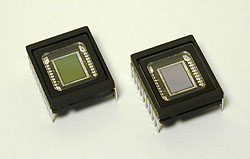
Sony ICX249AK (color) and ICX249AL (mono)

Shortly after I bought my MX7C I read that the hardware in the MX5C and MX516 were the same and all that needed to be substituted was the CCD chip. I contacted Terry Platt of StarlightXpress and asked if this was the same for the MX7C line of cameras. Happily this was the case and I put in an order for a Sony ICX249AL CCD chip directly to StarlightXpress.

Now why bother with a mono chip? Why the heck did I buy a color camera in the 1st place? Well, the convenience of 1 shot color is still a huge plus for me but the possibility of having a mono chip capable of taking more sensitive higher resolution luminance images to combine with color data was intriguing. Not having to buy another camera to be able to do this was what sold me though…

If you’re not squeamish about this sort of surgery, the swap is not hard to do and a fairly painless calibration is all you need to do to be up and running. However, I’ll insert the standard disclaimer here: This sort of thing voids your warranty. If you’re not comfortable or don’t know what you’re doing, try and arrange for the camera to be sent back to StarlightXpress or a local distributor and they will most likely do this for you. I have no affiliation with StarlightXpress nor is the information in this article endorsed by them in any way. Its something I did myself and wanted to document in case others out there were interested in doing the same.

The calibration instructions described here are adapted from a document provided by Michael Hattey of StarlightXpress. For the more technically inclined, you can download PDF spec sheets with very detailed information on these chips here Sony ICX249AK (Color) and here Sony ICX249AL (Mono). Note: I now have these spec sheets on my site instead of Sony, as they kee changing the links on me. Therefore there is a chance that they may be out of date. If you’re looking for up to the second info on these chips, please check Sony’s site at: http://products.sel.sony.com/semi/

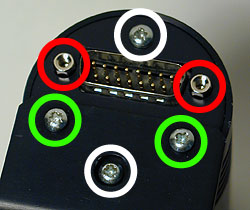
First lets take a look at opening the camera.

The picture to the right is confusing but there is method to the madness.

The view is of the rear of the camera. The 2 screws circled in green only hold the tripod adapter in place.

The screws circled in white attach the back plate to 2 long bolts that run the length of the camera that hold the optical window housing in place. These must be removed. (Be careful not to over tighten these when you put the camera back together!)

The hexagonal nuts circled in red hold the back plate of the camera to the 15 pin plug that is soldered to the circuit board. These must be also be removed.

Once the back plate and the camera housing have been removed you will notice a long brass bolt on each side of the camera.

These bolts hold the front part of the camera in place – the metal housing for the CCD to which the optical window is attached.

Be careful when removing these as the whole front of the camera will come off and the CCD enclosure is made airtight with

thermal heat sink grease as you can see in the picture on the bottom right. If you are going to do this it would be a good idea to get some computer silicone heat sink paste (a.k.a. thermal grease). at RadioShack or on-line.

The grease under the chip on my camera was completely dry and I had to clean it and reapply some. Remember though that a little goes a long way with this stuff!

While you’re at Radio Shack pick up an antistatic bracelet. CCD chips (like most electronics) can be easily destroyed by a static discharge and it is always good practice to keep yourself grounded.

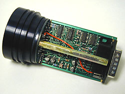
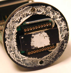
Here is a close up of the chip. The easiest way to remove it is with a thin flathead screwdriver like in the image or prying it up with an x-acto blade. Alternatively, places like RadioShack have specific tools for inserting and removing chips from sockets without damaging the pins.

The trick is to gently lift one end and then the other off of the cold finger until the chip comes loose. It is very easy to bend the pins if you aren’t careful.

Note the notch on the left side of the chip. This is not pin 1. (It is in fact close to pin 10) It is there, I assume, for leverage to make removing the chip from a socket easier. Pin 1 on these chips is marked by a circular indentation on the underside of the CCD.

Since the notch is easily visible I used it to mark the orientation of the chip in the socket. This is very important to take note of. If the CCD chip is incorrectly inserted you could destroy the CCD and possibly the camera. That said though, the Sony CCD chips are very similar and pin 1 (or 10) should be easy to identify.

I used a drop of liquid paper to mark the position of pin 10 on the cold finger for future reference.

In the bottom picture you see the cold finger with the CCD removed and dried grease I had to replace. The grease around the edge of the camera was thick but holding out so I left it. It is there to make the enclosure airtight and prevent moisture condensing and then freezing on the CCD chip as it cools down. This was a major problem I had with my CB245.

Installation of the new chip is easy – correctly orient the CCD in the socket, check that all the pins are entering the sockets correctly and press down gently and evenly putting pressure over the pins on each side. Its should just slide in…

This image shows the CCD mounting as seen edge on with the new chip installed. Under the CCD is the cold finger and under that is the TEC or Thermoelectric Cooling Device.

Once the new chip is installed replace the CCD housing and secure it with the long brass bolts. Do yourself a favor and make sure that the glass is very clean both on the housing and on the CCD window before closing it. Any dust specs on these surfaces will show up as circles or doughnuts (depending on your telescope) when you try to image forcing you to take flat field frames.

Don’t close the rest of the camera yet as we now have to calibrate it for the new chip. For calibration we will run a few tests with the camera open and running so adjustments can be made to 2 variable resistors located on opposite sides of the printed circuit board.

VR1 is located close to the center of the PCB and is pictured on the right. Click on the image for a close up.

First of all fire up the camera and take a test image through a pinhole or with a camera lens attached. Hopefully you’ll get a normal image and we can move on to dark frame adjustment.

If there is a problem, power off the camera and double check the obvious. If the problem persists try reinstalling the color chip and taking an image with that.

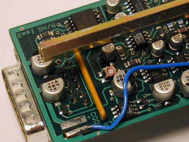
VR1 - Variable Resistor 1 (click for close up)

For the dark frame test we need to let the camera cool down for about 5 minutes. The cover the camera so no light can make it to the CCD chip (Remember how sensitive these chips are to light! I actually put my camera in a black cloth bag as well as covering the CCD.) and take a 1 second exposure and look at the histogram of the dark frame you just took.

The histogram of a properly calibrated camera should look a lot like the one on the above. (Note: I used the MX716 version of the software – StarlightXpress Star_MX7 v2.0e (04/06/2002)) There should no more than 1 or 2 entries in the VAL field and the values should range between 006 and 016. If the values are greater than 16, use a small flathead screwdriver to turn VR1 a few degrees anti-clockwise. Then take another 1 second dark frame and examine the histogram values to see if further adjustment is needed. If the values are lower than 6, use a small flathead screwdriver to turn VR1 a few degrees clockwise and repeat the dark frame histogram process until the values are correct.

After this process is complete it is a good idea to take a 5 minute dark frame to make sure the darks are free of hot spots bright streaks. There will probably be a brighter area in the upper left area of the frame. This is caused by the output amplifier and should be quite faint. If you have the chance it would be a good idea to compare your dark to the dark frame of a calibrated camera of the same type.

For the calibration of VR2 we are going to need a light with a narrow a beam as possible to simulate a star. There are 2 methods for doing this – one easy way is to shine a light or a laser at a spherical Christmas tree ornament to at a ball bearing and to focus the CCD and camera lens or telescope at the reflected beam.

The method I used was to tape a high power eyepiece to a flash light as seen in the image on the right. The eyepiece will focus (or narrow) the beam of light to a finer point. I used a University Optics 12.5mm Orthoscopic. I found the beam to be too bright even with the flashlight on the lowest setting so I added a variable polarizing moon filter to dim the light even more.

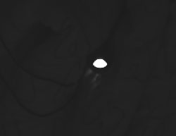
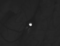
VR2 is located on the opposite side of the PCB towards the edge and front of the camera as seen in the picture on the right. This variable resistor controls the ABG (Anti-Blooming Gate) bias on the CCD chip. Anti-blooming prevents streaking and bloating of bright stars but slightly and affects linearity. ABG can be effectively turned off by turning this VR about 20° anti-clockwise.

To calibrate VR2 we need to focus the camera on a light source (as previously described) in a dark room and take a 1 second integration. My camera’s ABG bias was set too low and my image of the light source looked a like the image on the right. Instead of being as close to a point of light as possible, I got an oval due to “bleeding” caused by anti-blooming being almost set to the off position.

To calibrate the camera take a 1 second picture of your light source. If the resulting image looks like the middle picture on the right and/or if there is a bright streak in the image then the ABG gate is set too low. Turn VR2 a few degrees clockwise and take another integration.

If the image is gray or grainy then the ABG is set too high. Turn VR2 a few degrees anti-clockwise and take another integration to test the result. If you overshoot too much in the clockwise direction the camera sensitivity will be decreased by too much anti-blooming. If you overshoot anti-clockwise sensitivity will be higher but stars will be bloated and oval and streaks will appear so proper calibration is critical. This is the hardest and most painstaking part of the calibration to get right. My suggestion is to turn VR2 anti-clockwise until you get a bloated star image like mine and then take 1 second integrations turning VR2 clockwise 2 or 3 degrees at a time until the blooming just disappears.

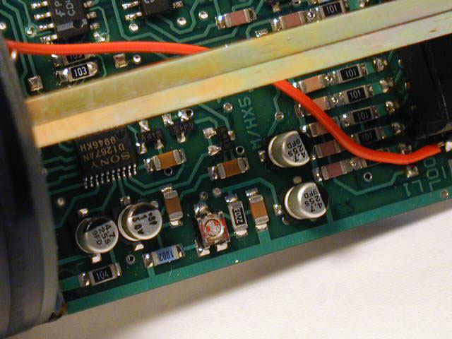
VR2 - Variable Resistor 2 (click for close up)

For the final step in calibrating the camera point it at a white target and take an integration that results in a mostly saturated image. Here I printed a 4 colored boxes and a thin crosshair for reference. The resulting histogram should have a major peak at a VAL of 255.

If the peak does not reach a VAL of 255 or if the image look gray or grainy then VR2 is set too far clockwise and you must go back and adjust it.

And that is it! You now have a MX7 with either the color or the mono chip installed, calibrated and ready to go!

Check my gallery to see images taken with both the MX7 and MX716:

http://astroturtle.com/imaging/

Comments Off on StarlightXpress MX7C to MX716 Conversion more...

Cookbook Autoguider

April 13 2003 update: Due to, among other things, time constraints and a brand-spanking-new MX7C, this autoguider is pretty much an abandoned project. Which isn’t to say that I won’t give folks a hand if they need it. I have some goodies that may be of help or at least a starting point for this project.

This is page will hopefully help some out there build the CCD Cookbook based autoguider circuit and provide some background on how to connect one to an LX50.

First of all I want to thank a good friend of mine, Michael McNeil over at http://www.caltel.com/~cno [on http://web.archive.org] for all the help and great advice.

This is really his baby as he put the board together for me leaving my limited knowledge of electronics to work out how to connect the thing to my LX50. Even then a good number of e-mails went back and forth reflecting on the pro’s and con’s of 74LS14’s… Sheesh!! :o)

This autoguider is an update of the version available in the CCD Cookbook which is based on the AY-3-1015D chip that is no longer in production and getting harder to find. The guider will work with the CB211 and CB245’s as well as with the old Connectix black and white parallel port quickcams thanks to Martin Niemi’s great autoguider software.

Here’s a link to Marty’s page [on http://web.archive.org]:

http://www.ameritech.net/users/mniemi000/auto.html

To the Cookbook autoguider page:

http://www.wvi.com/~rberry/cookbook/serial1.htm

Here are a couple of shots of Mike’s handy work. Component side and solder side. Everything was setup on a Radio Shack breadboard. Mike marked up the board with instructions even I can understand…

The box is just a regular plastic project box you can pick up at any electronic components shop. I chose plastic simply because I find it much easier to work with. All the holes in the box top were made first by melting away more or less the size I needed with a hot soldering iron and then just cutting and filing to a perfect fit.

I cut some foam for the top and bottom of the box. When the box is sealed it’s a snug fit and the foam holds everything in place. Here is the finished product hooked up and powered on! I really like the box I put together for this thing. Its solid, there are no bits falling off (thank goodness for glue guns!), and all the cables come off the thing to facilitate storage.

This is the pinout for the LX50 Autoguider port. The orientation is as if you were looking at the LX50 panel straight on. The best thing to do is just to get a ready made cable that is wired straight through.

You need a 6 pin RJ-12 plug. The pin numbering on these plugs is read from left to right (duh) with the plug held ‘upside down’. That means the little plastic flange that locks the plug is pointed at the ground, the embedded contacts are pointing up and the side the cable goes in is pointing towards you.

Here’s a screen shot from Marty’s program in action. One thing that had me confused the first night out is that if the guide star is too bright the program won’t lock on it. I was using a bright star just to make life easier but I eventually chose a dimmer star and threw my Hartmann mask on the scope for good measure and everything went great from there.

In my case, the calibration routine threw the guide star right off the frame in the Y-axis the first couple of times. Try, try again and start the calibration with the guide star as close to center as possible!

Click image for larger version


Centering the CB245 CCD chip

If you’ve enjoyed these tips and are in the market for electronics or photo gear, using these links to buy from TigerDirect or Amazon.com or alternatively using the PayPal Donate button to make a small contribution helps me keep this site going. Thanks!

The very fist thing I noticed after the first night imaging with my CB245 was how badly I had centered the CCD and the cold finger. Objects I wanted to image were not only completely out of the FOV of my illuminated 9mm reticle but also almost out of the FOV on my 26mm Plössl! Finding things was just a completely ludicrous waste of time. After asking around on the CCD list and realizing that nobody had any tips on and easy way to do this I decided to start rubbing my 2 remaining neurons together to see if I could maybe get a spark.

The idea I came up with was pretty simple. If I could get the CCD to see a perfectly centered crosshair I could then move it into the right spot.

Great! Easy! I pulled off the top of the camera head and traced a circle around it. Found and marked center with a compass and then drew a crosshair through it.

I placed the camera head cap on top of the crosshair drawn on paper and made sure the cap was centered in relation to the circle around it.

Now for the hard part: Going in to my mom’s sewing stuff. After a few mumbles and threats I managed to grab a spool of the thicker type white thread that I taped into place in line with the crosshairs.

In the first image you can see the cap with the threads and in the next one everything mounted and ready to go on the scope for testing. I made an aperature mask out of cardboard with about a dime sized hole in it. Fired up Win245 and played with find mode untill I could see something.

In the first image below you can see the best I could do to center the chip by eye. The next one is after only about 2 or 3 tweaks of the position of the cold finger. The last image is of the top of a lamp post about 15 meters away.

The little ball centered in the Meade 9mm illuminated reticule ep’s FOV and then switched for the CB245 and presto! Quick and dirty centering of your ccd in 15mins or your money back! Now if it would only stop raining! ;o)

Before

After

Test Image


CCD CookBook CB245

First of all my electronics knowledge is little or none. Sure I’ve had to learn a bit in the process of putting this thing together but I still consider myself a complete newbie when it comes to reading a wiring diagram or even figuring out how to wire 2 transformers together. If you fit this description this is not exactly an easy project but if you are patient and are willing to learn, adapt, and implement modifications to suit your needs it is an immensely enjoyable and ‘doable’ project.

Berry, Kanto, and Munger have put together an incredibly simplified and unbelievably robust project. My list of boo-boo’s in building this have been long and severe but somehow its kept on ticking and is finally ready to take some pics. This thing surviving my building it is an achievement in itself! ;o)

Also keep in mind that it is not an elegant solution. There are wires running everywhere, water cooling is a pain, and every once in a while something will probably stop working, forcing you to drag out the Cookbook, multimeter, and the soldering iron and do some detective work. If you want something you can bang on the back of your scope to take pictures and not have to worry about anything else get an ST4 or a Starlight or something. But if you’re a tinkerer, and if you want to learn not only about how to take pictures but also about how a CCD works, and especially if you’re on a budget this project is a whole lot more fun…

Besides, the finished product is yours. By that I mean, (good or bad), there’s not another one out there exactly like it.

And never forget help is always available on the mailing list. The people on this list have been incredibly patient and completely indispensable in helping me put this thing together. (Thanks guys and gals!) You can subscribe to the mailing list on the AstroArchive web page and its called the “Homebuilt CCD” list.

Well now that I’ve gotten off of my soapbox let me tell you about how I’ve built this thing.

The power supply and interface are housed in an old external SCSI drive bay. There was plenty of space for everything and I decided to leave the SCSI power supply in (board at the top) to feed the Peltier off of the 5v it provides. I wired everything to the same AC input and switch and also used the SCSI power supply to power a fan, led’s, etc.

Next down you can see a couple of 12v/500ma transformers. I had to opt for this solution because I simply could not track down a 15v/500ma supply here in Portugal. Silly huh? Anyway this setup gives me about 17v which is within spec and so far has been working great.

The bridge and 4700uF capacitors have been glued with a glue gun to the back of the box.At the bottom you can see the interface board and the heat sinks which barely fit.

Here is the closed box. From the left is the connection for the Peltier from the SCSI supply, then the fuse, power led, the signal shield jack, and 2 female DB25 connectors for the camera head and computer… (have to label those!)

Surprisingly I’m getting a very clean image even with everything stuffed into the same box. From what I read on the CB list I was expecting to get of lot of interference from the power supplies sitting next to the interface board. On the first night out I did 2 min integration’s and got very clean images none the less. Lucky me?

For the camera head I didn’t deviate at all from what’s in the CookBook. I tried some wacky ideas that went very badly and quickly decided to stop trying to be a smart ass and follow the instructions provided. For the newbies: Boy are you going to have fun with this part! Little tip: look for 16 pin ribbon cable connectors like the ones used for connecting IDE drives. Long ago the 16 pin ones were used to connect joysticks but I’m sure they’re still pretty easy to find. The plastic connector can be easily trimmed down to fit in the opening on the camera head and epoxied into place. Worked for me!

“First light” was on the 3rd of October, 2000 at 00:56UT with the camera head on the table and a 50mm Canon lens on top of it. I taped a Kodak film box top to the ceiling and hoped for the best…

Check out my CB245 gallery for images taken with this camera:
http://astroturtle.com/imaging/

I’d like to end this by leaving some links for would be CB245’ers:

Richard Berry’s CookBook Home Page
http://www.wvi.com/~rberry/cookbook/cookbook.htm


Win245 CookBook control software by Tybee Evans
http://www.intricate-ms.com


MouseCam – Conectix QuickCam Mods

I finally managed to track down a used Conectix black and white wecam on E-bay and after a few weeks I was testing and tweaking to my hearts content.

I quickly realized I was going to need some sort of box to put this thing in so it would
attach to the scope more easily.

After rummaging around some old computer equipment at the office I came across an old IBM PS/2 mouse. Hey, the dimensions were right… Its really light, the hole at the bottom seemed the right size… Well why the heck not??

As it turns out the hole on the bottom where the mouse ball goes in is the exact size of a 35mm film canister. I had to break off and sand down the plastic that held the ball cover in place. Not too much as I was going for a tight fit. If fact the fit turned out to be so good that I didn’t even bother to glue the canister in place.

I had a laugh when I discovered that the IBM mouse’s guts were made by Logitech. How ironic… (Conectix was bought by Logitech.)

On the inside of the mouse the Conecix PCB fits perfectly and the cable is about the same size as the old mouse cable so I could use the plastic guider and retainer that was already part of the mouse housing.

To hold the wecam board in place first I made an outline with an permanent marker of where I wanted it to stay, and eyeballed more or less the best places for the screws to go and marked them as well. Then I took one of the thicker type paper clips and heated up with a lighter and melted guide holes through the marks I had made.

For the bolts, I ransacked a couple of old serial cables. The type that go from the mother board and end in a 9 or 25 pin D connector on the computer box where you plug in your mouse or modem or whatever usually have a hex-nut that is the perfect size for this job.

I removed the hex nut with the screw and the little bolt on the inner side of the 9 pin connector and used the hex nut on the inside of the mouse and the bolt on the under side to tighten it in place.

The Conecix board is held in place by a strip of plastic I cut out of an old QIC-80 tape
box. It was easy enough to cut with scissors without breaking. I made melted a whole on either end with a paper clip and threaded two more hex nuts. This was then screwed on top of the circuit board into the hex nuts already in the mouse body. (as seen in the picture below) Nice tight fit. and all ready to close up and pop it on the scope.

And here’s a bottom view of the finished product. It is very easy to align the CCD to
center as the fit is tight enough to hold the board in place from an occasional bump, but not tight enough to keep you from putting it back into place with your fingers if the alignment goes off.

Eventually I’m going to try to setup a computer fan on the other side of the mouse so I can cool my… MouseCam!

One great thing I discovered is that since the ccd chip is much closer to the eyepiece
than in the regular ball housing the camera is now very close to par-focal with my Meade 9mm illuminated reticule eyepiece.

Hey! Whats that on your OTA?!? If nothing else a mouse hanging off the back of your telescope does attract a lot of attention. My father and I had a laugh at how ridiculous the thing looks on the LX50. But, hey… Its works!

Check my astro gallery for images taken with modified webams like this one: http://astroturtle.com/imaging/


Copyright © 1996-2010 astroturtle. All rights reserved.
Jarrah theme by Templates Next | Powered by WordPress